
Reflex Action Game
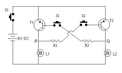
The circuit operates using two NPN transistors, TR1 and TR2, which are responsible for controlling the lamps L1 and L2. The configuration ensures that when one button is pressed, it activates its corresponding transistor while simultaneously preventing the other transistor from conducting. The circuit relies on the principle of transistor switching, where the application of a voltage at the base terminal allows current to flow through the collector-emitter path.
In the initial state, with switch S3 in the ON position, both transistors are in a non-conducting state. As soon as one participant presses their button, the corresponding transistor is biased into conduction. For instance, pressing S1 sends a negative voltage through R1 to the base of TR1, turning it on. This results in lamp L1 illuminating, indicating that participant one has pressed their button first. The drop in voltage at point P effectively disables TR2, ensuring that lamp L2 remains off.
This design is particularly effective in quiz scenarios where quick response times are crucial. The circuit's simplicity allows for easy implementation and troubleshooting, making it suitable for various educational and competitive environments. The choice of components, such as the transistors and resistors, should be made based on the required current and voltage ratings to ensure reliable operation. Overall, this circuit provides a straightforward and effective solution for determining the first responder in quiz competitions.This is a very interesting and simple circuit. This also can be used in quiz events, where two participants hit their button to answer. The participant, who pressed his button first, will get a chance to answer first. This circuit will resolve which participant hit the button first, by glowing the lamps associated with the button. When S3 is in ON position, base circuits of both the transistors remains open and thus no current flows in their respective collector-emitter circuits. Hence, both the lamps remain off. Now, let S1 be pressed first, the transistor TR1 gets negative base voltage through R1. Due to this transistor TR1 starts conduction, and lamp L1 begins to glow. On account of this action the voltage at point P drops to nearly zero value and if the push-button S2 is pressed in this condition, the transistor TR2 gets no base voltage and it will remain non-conduction.
Similarly when S1 is pressed first, the lamp(L2) associated with S1 will glow preventing L1 to glow. Since, at a time only one lamp will glow, this circuit will always give correct judgment. All the material on this website is copyright property of Material on this site is for personal use only and can not be used for any commercial activity without written permission of Use the information provided within this website at your own risk. Information within this website is provided as-is without warranty or guarantee of any kind. Please read Copyright and Disclaimer notice carefully. 🔗 External reference
Related Circuits
Circuits that utilize large value resistor and capacitor combinations tend to lack accuracy due to the wide tolerance and leakage current of polarized capacitors. A more effective approach is to implement an astable circuit in conjunction with a binary...
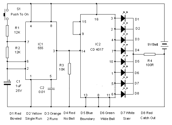
This electronic cricket device is a gift for children. This simple battery-powered circuit can be used to simulate a cricket match with friends. Each LED in the circuit represents various statuses of the cricket match, such as a six,...

R14 is configured to establish an initial "starting" speed for the oscillators U1A and U1B. As capacitor C2 charges, the oscillation gradually slows down during the discharging phase of C2, creating a roulette-wheel effect on LED S1 through resistor...

The objective of the circuit is to create an electronic dice using the functionality of a 555 timer integrated circuit operating in astable mode. The electronic dice circuit utilizes a 555 timer configured in astable mode to generate a series...
The PC board has been designed to accept either a PIC16F84A or PIC16F628. With the introduction of the 628 to the world market, it has taken over from the PIC16F84A and we will be ceasing to design projects for...
The objective is to enhance information transmission through the distribution of articles. For any issues related to article content, copyright, or other concerns, please contact us via email at [email protected] within 15 days. Prompt action will be taken to...