
Relative Field Strength Meter For A DMM
Passive field strength meters are essential tools used for measuring electromagnetic fields. The design of these meters often incorporates a 50mA analog meter movement, which is a critical component for achieving adequate sensitivity in the measurements. The analog meter movement operates by converting the electromagnetic field strength into a corresponding mechanical movement of the needle, allowing users to visually interpret the field strength levels.
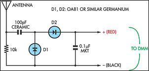
The circuitry of a passive field strength meter typically includes an antenna, which captures the electromagnetic waves. The captured signals are then fed into a rectifier circuit that converts the alternating current (AC) signals into direct current (DC) signals. This rectified output is proportional to the strength of the incoming electromagnetic field.
The analog meter movement is connected to the output of the rectifier, where it translates the DC signal into a readable deflection on the meter scale. The sensitivity of the meter can be adjusted by incorporating resistors or variable potentiometers in the circuit, allowing for calibration based on specific measurement requirements.
In addition to the basic components, passive field strength meters may also include filter circuits to eliminate noise and improve measurement accuracy. These filters can be designed to target specific frequency ranges, enhancing the meter's performance in various applications, such as telecommunications, broadcasting, and RF engineering.
Overall, the design and implementation of passive field strength meters involve careful consideration of component selection and circuit design to ensure reliable and accurate measurements of electromagnetic fields.Many passive field strength meters have appeared in the past, typically using a 50mA analog meter movement if reasonable sensitivity was to be obtained. T.. 🔗 External reference
Related Circuits
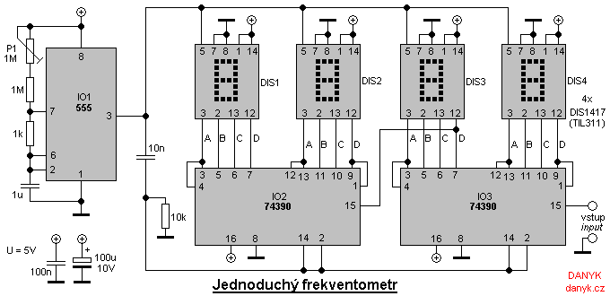
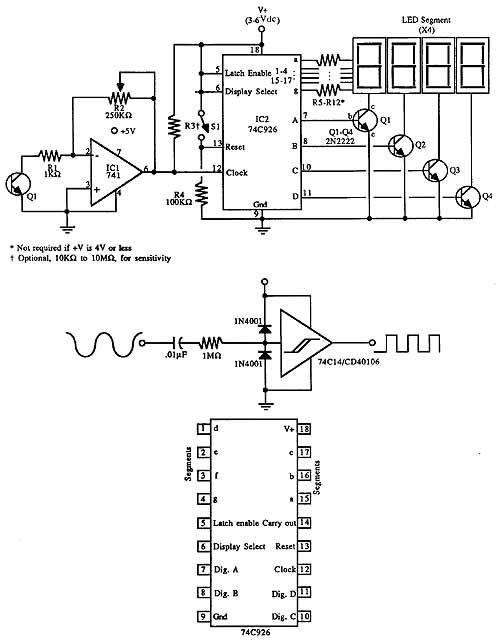
A simple digital frequency meter has various applications, serving as an experiment for beginners, laboratory equipment, or a meter integrated into certain devices. It is ideal for situations where frequency measurement and digital display are required. The frequency meter...
Many analog ohm meters have a non-linear scale, which results in poorer resolution at higher resistance values. This is due to the use of inexpensive current sources. Many analog ohm meters operate on a principle where the scale is not...
A simple LED-based voltmeter is required to monitor the voltage of a variable power supply. The proposed LED voltmeter circuit utilizes a series of light-emitting diodes (LEDs) to visually represent the voltage level of a variable power supply. This...
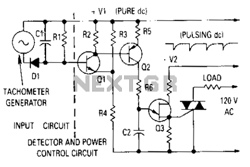
The generator output is rectified, filtered, and applied between the positive supply voltage and the base of the detector transistor. This configuration provides a negative voltage that reduces the base voltage as the speed increases. During normal operation, if...
Michelson was the inventor of a unique interferometer that opened up new vistas in the science of light and optics. With the interferometer, Michelson was able to determine, with unprecedented accuracy, the speed of light, the wavelength and frequency...
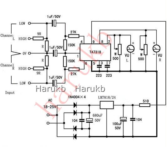
VU Meter Driver PCB Completed Board Stereo for Two VU Meters Audio Amplifier. VU Meter Driver PCB Completed TA7318P Board Stereo for Two VU Meters Features: Specifications: Power voltage: AC 20V to AC 26V (not more than 26V) size:...