
Electromagnetic Ring Launcher Circuit
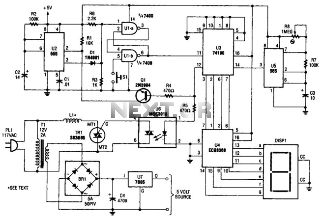
The electromagnetic ring launcher circuit is a sophisticated assembly designed to illustrate the principles of electromagnetic propulsion. The clock circuit, centered around the U5 component, operates as an astable multivibrator, generating a continuous square wave signal. This signal serves as the timing reference for the subsequent subcircuits. The countdown/display circuit is critical for user interaction, featuring the U3 synchronous up/down counter, which counts down from a preset number of seconds to launch. Its BCD outputs are processed by the U4 ECG8368, which converts the binary-coded decimal data into a format suitable for display on the common-cathode seven-segment display (DISP1).
The trigger circuit is essential for initiating the launch sequence. It utilizes the MOC3010 optoisolator to safely isolate the control logic from the high-power components. The output of the optoisolator drives the TR1 Triac, which handles the high current required to energize the repulsion coil (L1). The repulsion coil generates a magnetic field that interacts with the metal ring, creating a force that propels the ring along its path.
The reset circuit is designed to ensure that the system can be easily reset between launches. It employs the U1 NAND gate to manage the reset logic, while U2 acts as a monostable timer, providing a controlled pulse to reset the countdown and prepare the system for the next launch sequence. The integration of these components allows for a smooth operation, demonstrating the principles of electromagnetic repulsion effectively. Overall, the design emphasizes safety, functionality, and user interaction, making it an educational tool for understanding electromagnetic principles. The electromagnetic ring launcher is comprised of.four subcircuits: a clock circuit (built around U5, a 555 oscillator/timer configured for astable operation), a count-down/display circuit (built around U3), a 74190 synchronous up/down counter with BCD outputs that is configured for countdown operation; U4, a ECG8368 BCD-to-7-segment latch/decoder/display driver; and DISP1, a common-cathode seven-segment display), a trigger circuit (comprised of U6), an MOC3010 optoisolator/ coupler with Triac-driver output; TR1, an SK3665 200-PIV, 4-A Triac; and a few support components), and a reset circuit (comprised of Ul, a 7400 quad 2-input NAND gate; U2, a second 555 oscillator/timer configured for monostable operation; and a few support components). This circuit is that of a repulsion coil (LI) used to demonstrate the principle of electromagnetic repulsion by propelling a metal ring around the core of LI through the air.
A countdown circuit is provided to count seconds before launch. 🔗 External reference
Related Circuits
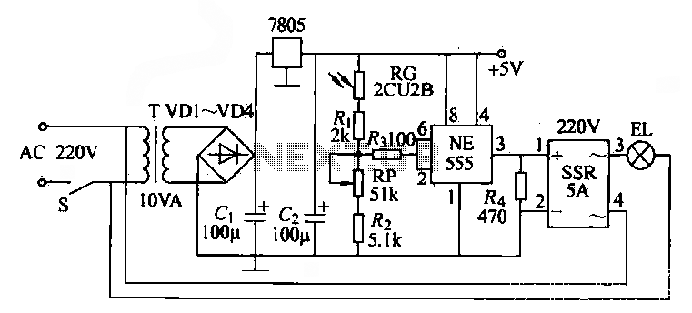
The NE555 time base circuit with an AC solid-state relay (SSR) can function as an automatic light switch circuit. The circuit diagram illustrates that during the day, the incandescent light is turned off due to the influence of the...
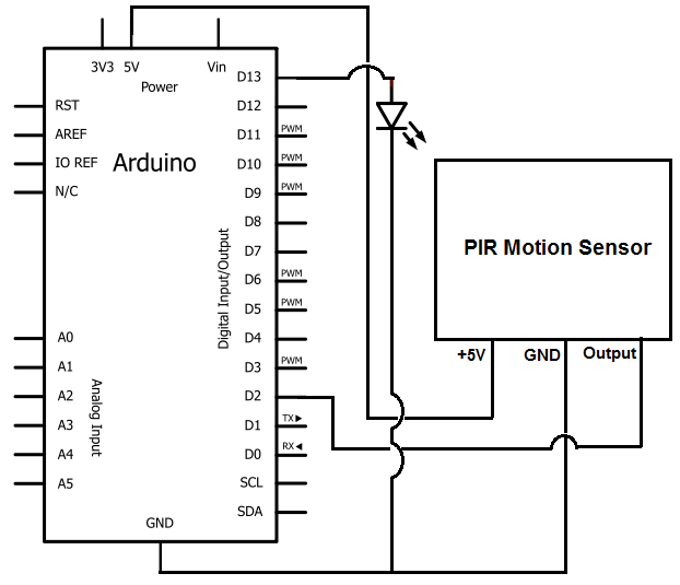
Once the motion sensor detects motion, the Arduino can be programmed to activate an LED, turn on a motor, sound a buzzer, etc. In this circuit, for simplicity, an LED will be turned on when the motion sensor detects...
This version sports a 2nd audio amplifier stage at Q3. The output level with this version is sufficient to drive a crystal headphone to a comfortable volume. The "crystal" headphone is like those used on ye olde crystal radios....
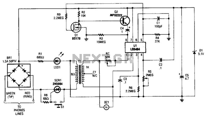
The LS3404 melody chip is activated when the hold switch (SI) is pressed, causing SCR1 to conduct and maintain the telephone line through Tl, Rl, and LED1. The voltage across Rl and LED1 is utilized to power the melody...
This process can be simplified by utilizing a display kit from PJRC, which includes the appropriate firmware installed on the display, a functioning pushbutton board, and the necessary cables. The PJRC display features a 4-pin connector compatible with the...
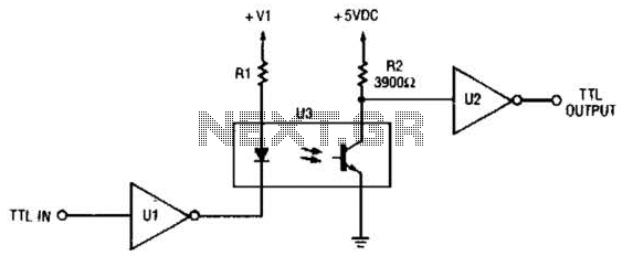
This circuit is a TTL-to-TTL isolator circuit. The driver circuit is an open-collector TTL inverter (U1). When the input is high, the output of the inverter is low. Thus, when the input is high, the output of U1 grounds...