
Digital Volume Control
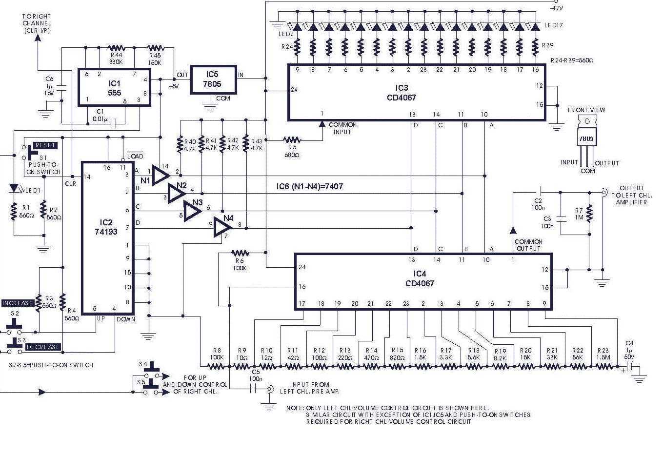
The circuit described is a digital volume control system that utilizes six integrated circuits (ICs) to manage audio levels electronically. The main components include a 555 timer configured as an astable multivibrator (IC1), which generates a square wave signal. The frequency of this signal can be modified by selecting appropriate resistor values (R44, R45) and a capacitor (C6), allowing for a period of 0.3 seconds as specified.
IC2 serves as a presetable up/down counter, which is essential for tracking the volume changes. In this configuration, the up mode increments the volume while the down mode decrements it, providing a straightforward user interface for volume adjustments. The counter's output is in Binary-Coded Decimal (BCD) format, making it suitable for digital applications.
Analogue multiplexers IC3 and IC4 play critical roles in the circuit. IC3 is utilized as a level indicator, likely providing visual feedback on the current volume level, while IC4 acts as a digital potentiometer, facilitating smooth transitions in volume levels without the mechanical wear associated with traditional potentiometers.
The system initialization requires the pressing of switch S1, which resets the entire circuit to a known state. Subsequently, switch S2 can be activated to enable the counting process, allowing the user to adjust the volume by counting the pulses generated by the 555 timer.
Finally, IC6 functions as an interface between TTL (Transistor-Transistor Logic) and CMOS (Complementary Metal-Oxide-Semiconductor) technologies, ensuring compatibility between different logic levels in the circuit. This integration of components results in an efficient and reliable digital volume control system suitable for various audio applications.Circuit of a digital volume control using six discrete ICs, including a 5V regulator, is presented. IC1 (555) is configured to function as astable flip-flop. Its frequency or period may be adjusted by proper choice of resistors R44, R45 and capacitor C6 combination. Here it is for 0.3 second period. IC2 is a presetable up/down counter. In this circuit up-mode is used for increasing and down-mode is used for decreasing the volume. IC3 and IC4 are 16-channel analogue multiplexers which function as analogue switches. Here IC3 is used as level indicator while IC4 is used as a potentiometer. Soon after the power is switched on, switch S1 is to be pressed to reset the whole system. When switch S2 is pressed, IC2 counts up the number of pulses and the result is available in the form of BCD output. IC6 is used as an interface between TTL and CMO 🔗 External reference
Related Circuits
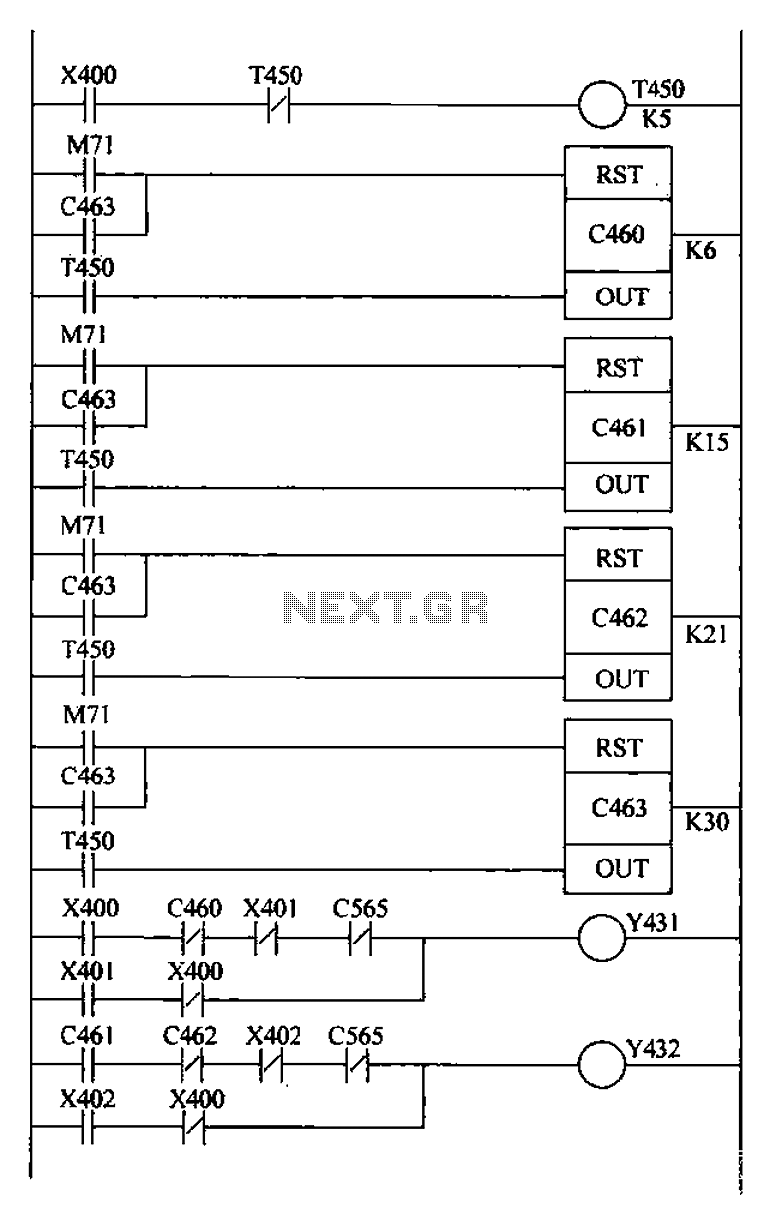
Bridge crane control PLC ladder design includes a detection retract mechanism for ladder hiding, programmed for both manual and automatic operation. The system operates as follows: 1) Upon PLC boot-up, an initialization pulse is generated by internal relay M71,...
The ELM622 by ELM Electronics is a preprogrammed PIC that converts commands from a Sony infrared remote control into a serial data stream. An IR receiver utilizing the ELM622 does not require kernel modifications. This project demonstrates how to...
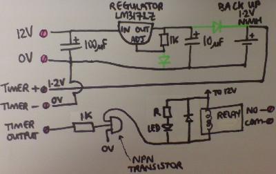
Most supermarkets today offer plug-in mains-powered digital programmable timers. These devices are designed to automatically turn lights on and off, activate washing machines while the user is away, and more. Prices start at around £5 ($10), and these products...
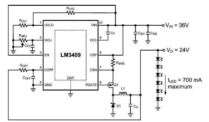
This dimming-controlled LED driver electronic circuit requires an input voltage of 36 volts and will provide an output voltage of 24 volts at a maximum current of 700 mA. The described dimming-controlled LED driver circuit is designed to efficiently convert...
Digital-ProfiLab was designed for measurement and control applications, combining features like circuit and logic simulation, front panel design, and hardware control to one powerful tool. Incoming signals from external devices may be processed and displayed. A circuit editor is...
This audio mixer circuit schematic is designed around four current-controlled amplifiers, all integrated within the SSM2024 IC. The audio mixer circuit utilizes the SSM2024 integrated circuit, which features low-noise, high-performance operational amplifiers suitable for audio applications. The SSM2024 is particularly...
Warning: include(partials/cookie-banner.php): Failed to open stream: Permission denied in /var/www/html/nextgr/view-circuit.php on line 713
Warning: include(): Failed opening 'partials/cookie-banner.php' for inclusion (include_path='.:/usr/share/php') in /var/www/html/nextgr/view-circuit.php on line 713