
tonefrequency detector circuit

The tone/frequency detector circuit is engineered to identify specific audio frequencies and is particularly useful in applications such as signal processing, telecommunications, and audio systems. The LM567 integrated circuit serves as the core component of this design, functioning as a phase-locked loop (PLL) to detect the presence of a specific frequency signal.
In this configuration, the circuit employs an I (in-phase) and Q (quadrature) detection scheme, which enhances the accuracy of frequency detection. The voltage-controlled oscillator (VCO) within the LM567 generates a reference frequency that can be adjusted to match the desired tone frequency. This allows for flexibility in tuning the circuit to different frequencies as required by the application.
The external components, such as resistors and capacitors, play a crucial role in determining the center frequency and bandwidth of the detection. By selecting appropriate values for these components, the user can customize the response of the circuit to be more or less sensitive to variations in signal frequency. Additionally, the output delay can be adjusted to ensure that the detector responds appropriately to transient signals without false triggering.
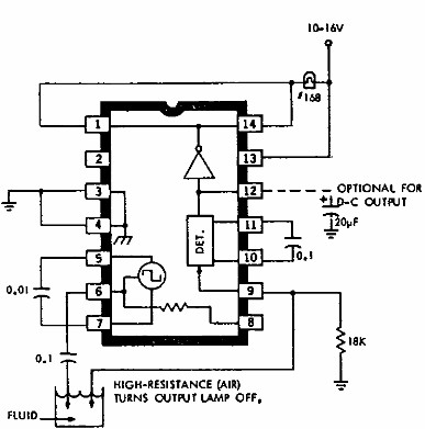
The output stage of the LM567 provides a saturated switch that can be interfaced with other components in the system, such as microcontrollers or relays, allowing for seamless integration into larger electronic systems. Overall, this tone/frequency detector circuit provides a reliable solution for monitoring and responding to specific audio signals in a variety of electronic applications.This is a design circuit for tone/frequency detector (decoder) circuit that can be used to detect the presence of a signal with a certain tone. The output of the circuit will be active if the signal is the same tone with the tone of a series of internal oscillator.
LM567 is one of decoder that we can use. This is the figure of the circuit; The LM5 67 and LM567C are general purpose tone decoders. Both are designed to provide a saturated transistor switch to ground when an input signal is present within the pass band. The circuit consists of an I and Q detector. Both, I and Q detector are driven by a voltage controlled oscillator which determines the center frequency of the decoder.
To independently set center frequency, bandwidth and output delay, external components are used. 🔗 External reference
Related Circuits
This electronic liquid detector circuit diagram utilizes the ULN2429A monolithic bipolar integrated circuit, which is designed to detect the presence or absence of various types of liquids. The detection mechanism involves comparing the resistance of a probe immersed in...
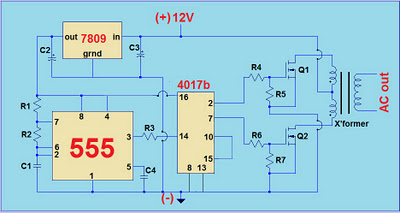
This project involves a simple 12V to 220V modified sine-wave inverter utilizing a 555 timer IC and a CD4017 decade counter. The inverter is capable of delivering 300W of continuous power and approximately 500W of maximum power output for...
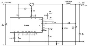
The circuit illustrates a TL494 pulse width modulated step-down converter schematic. This circuit allows for testing of line regulation, load regulation, output ripple, short circuit current, and efficiency under various input voltage conditions. A detailed table of these tests...
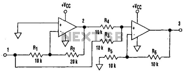
It is well understood that utilizing single-supply operational amplifiers (op amps) can present challenges when implementing simple functions in a bipolar signal environment. Often, this necessitates the use of additional op amps and other electronic components. Considering this, it...
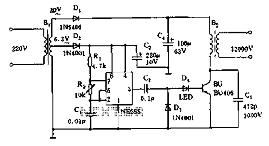
The neon voltage power supply circuit is straightforward to construct, offering stable output power and other desirable characteristics. The core component of this circuit is the NE555 timer, which generates a high-frequency oscillation signal in the range of 15...
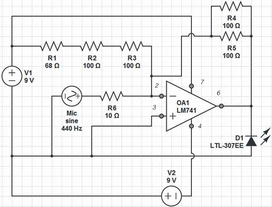
Red = V+, Black = V-, Green = GND, Yellow = Mic Input, Orange = LED Output. The op-amp used is an LM741, which is intended to adjust the peak brightness of the LED based on the ambient sound...