
Remote antenna for 60 kHz (WWVB) reception
The described system utilizes an amplifier circuit housed within an outdoor enclosure, which is critical for enhancing the signal received from a designated antenna. The four capacitors on the perfboard play a pivotal role in tuning the receive loop to resonate at the desired frequency, optimizing signal capture. The challenge presented by the physical environment—specifically, the steel and reinforced concrete structure of the office building—complicates the reception of low-frequency signals like the 60 kHz time signal from the NIST station.
To address the inadequate signal reception within the conference room, an external receive antenna is strategically positioned on the building's roof, where the signal strength is significantly better. This antenna is connected to the amplifier circuitry, which boosts the signal before it is transmitted to the conference room. The design must ensure minimal signal loss during transmission, which could be achieved through the use of low-loss coaxial cables and appropriate impedance matching techniques.
Once the amplified signal reaches the conference room, it is coupled to the atomic clocks. This coupling may involve additional circuitry to ensure compatibility between the output of the amplifier and the input requirements of the clocks. The entire setup is designed to provide reliable synchronization of the atomic clocks with the WWVB time signal, thereby overcoming the challenges posed by the building's construction and electronic noise interference. Proper grounding and shielding techniques should also be implemented to further enhance signal integrity and reduce susceptibility to electromagnetic interference.Inside the outdoor box to which the loop is mounted showing the amplifier circuitry. The four capacitors visible at the lower-left corner of the perfboard are used to broadly resonate the receive loop. In the office building in which he worked (a city government building near downtown Salt Lake City) there was a conference room with a pair
of "Atomic Clock" receivers on a middle floor. Being that this was a modern building of steel and reinforced concrete construction, and because it was full of electronic devices such as computers, fluorescent lights, etc. neither of these receivers ever managed to get a good enough signal to synchronize themselves to the 60 kHz time signal being transmitted from Fort Collins, Colorado by the NIST station, WWVB even though the signal from that station here in the Salt Lake area is quite strong.
The solution was to bring a signal into the room from outside, a project that would involve a receive antenna placed in a location that did have a good signal - such as the roof of the building - and then convey it to the conference room and somehow couple it to the clocks in question. 🔗 External reference
Related Circuits
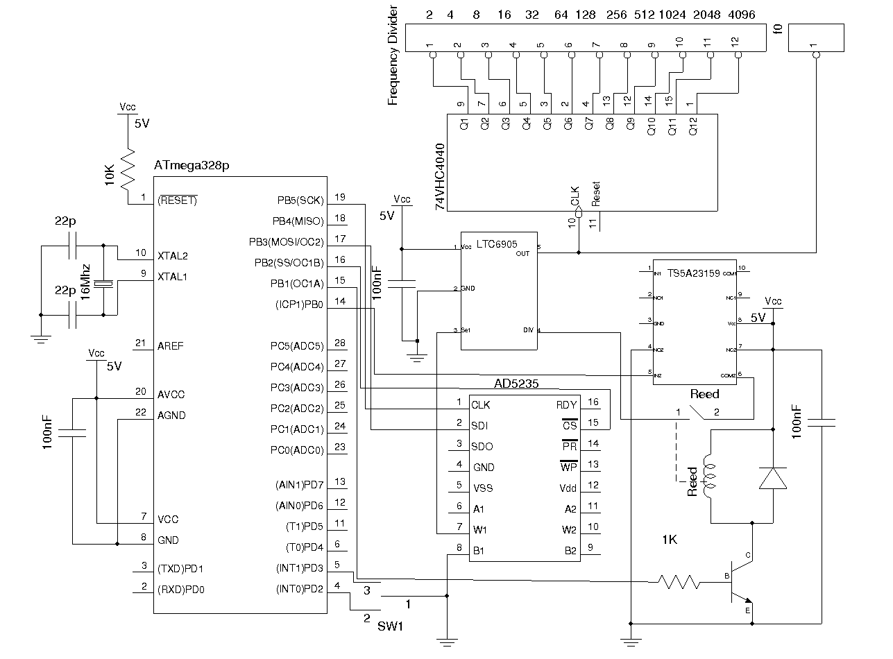
Most commercial-grade signal generators provide more than just sinusoidal waveform output, but they tend to be expensive for casual use. This article presents a simple wideband signal generator built around Linear Technology's LTC6905 Silicon Oscillator, capable of generating frequencies...
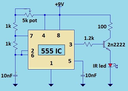
It is necessary to adjust the 10K potentiometer while aiming the device at the television to obstruct the infrared rays from the remote control. This adjustment can be achieved through a process of trial and error. The circuit in question...
The form of a musical signal never resembles a square wave. The frequency range perceived by an average adult rarely exceeds 17 kHz. Therefore, the appropriateness of testing audio amplifiers with a 100 kHz square wave signal is often...
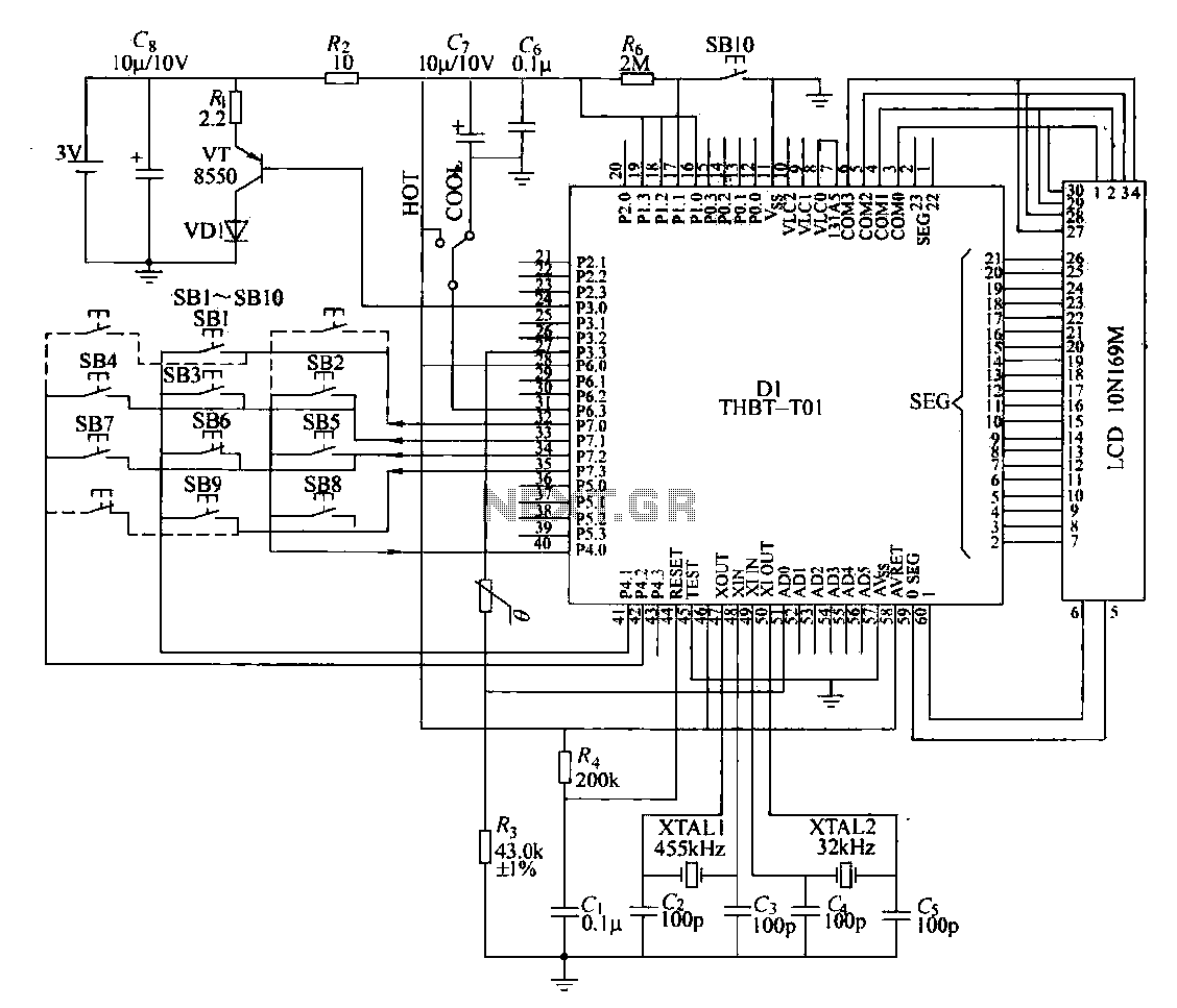
The circuit composition of a specific remote control transmitter is illustrated in a diagram. The transmitter primarily consists of a large-scale integrated circuit chip (D1, THBT-T01), a 4.5 kHz crystal oscillator, a 32 kHz crystal oscillator, a liquid crystal...
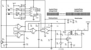
A circuit designed to block a television and any selected device from receiving signals from a standard remote control. This project involves converting an ordinary remote into a jamming device while maintaining its normal functionality. The chosen remote control...
The following circuit illustrates a schematic diagram for a remote control toy car. Features: it does not affect the performance of the original design. The remote control toy car schematic circuit diagram typically consists of several key components that work...