
Remote control transmitter circuit
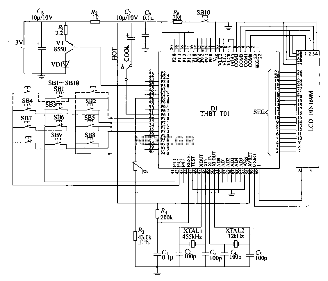
The dual clock pulse oscillation circuit employs a crystal (XTAL1), capacitors (C2, C3, 100 pF), and D1 to form a 455 kHz oscillator. This oscillator generates a pulse signal, which is then divided to produce 38 kHz carrier frequency pulses. A second crystal (XTAL2), capacitor (C4, 100 pF), and integrated circuits (D1) create a 32 kHz vibrator (with a precise value of 32.708 kHz), whose output clock signal is utilized for the main circuit and the LCD.
The scan pulse generator is produced from the outputs of D1, with the key signal compression encoder receiving inputs from the key matrix. The output and input terminals form a 4x3 key matrix, allowing for 12 function keys. Although there are 12 keys, only nine are actively used, with six keys (SB2 to SB7) having dual functions. During operation, the microcontroller outputs scanning timing pulses. The microcontroller (D1, 80-pin plastic quad flat package) is powered by a 3V supply through a resistor (R2). The integrated circuit contains a frequency divider, data register, timing gate, controller (for coded modulation), and keyboard input/output circuit.
The keyboard matrix circuit consists of a 4x3 matrix switch. This circuit, along with the scan pulse generator and signal encoder circuit, facilitates key command input. The key input circuit processes the matrix pulse signal to output corresponding code addresses to the data register, which is a read-only memory (ROM) pre-stored with operational codes. When a function key is pressed, the intersecting lines close, allowing the corresponding address in the ROM to be read and converted into binary coded instructions for the remote control receiver's microprocessor.
In the encoding, modulation, drive, and transmission circuit, the encoder modulator modulates the 38 kHz carrier frequency signal with the coded instructions to produce a modulated signal. This signal is then buffered and output from pin 24 of the microcontroller to the base of the excitation tube (VT), which amplifies the infrared LED's output, emitting the modulated 38 kHz signal into space through the transmitter's radiation window.
The liquid crystal display circuit utilizes an LCD, which requires alternating polarity AC square wave voltage to display characters and numbers. The connections from the microcontroller (D1) to the LCD include common electrode pins (COM0-COM3) and segment pins (SEG) that connect to the appropriate display fields.
Additional components include a reset terminal pin on the MCU (D1), an external reset resistor (R), and a capacitor (C1) to ensure the transmitter operates correctly at startup. The transmitter's instructions are transmitted as 32-bit binary code, with pulse width spacing denoting "0" and "1" codes.Specific remote control transmitter circuit composition shown in a diagram. Transmitter mainly by the large scale integrated circuit chip Dl (THBT- T01), 4s5kHz crystal oscillator, 32kHz crystal oscillator, a liquid crystal display (LCD), room temperature thermal sensing thermistor RT, an infrared light emitting diode (LED), incentives transistor VT, keyboard switch matrix circuit and other components. The transmitter is powered by two AA batteries, the voltage is 3V. 2) dual clock pulse oscillation circuit: The transmitter uses dual clock pulse oscillation circuit, wherein a crystal XTAL1, capacitors C2, C3 (lOOpF) and Dl of @ @ foot composed 455kHz oscillator when God, 455kHz oscillator after generating a pulse signal by dividing 38kHz carrier frequency pulses.
By the crystal XTAL2, capacitor C4, G (lOOpF) and integrated circuits @ @ D1 7 feet composed 32kHz (the exact value is 32. 708kHz) vibrator Ge, whose output clock signal for the main circuit and a liquid crystal display circuits.
3) Scan pulse generator: Dl of @ ~ @ feet 4 outputs a scan pulse generator, @ ~ @ foot is the key signal compression encoder 3 inputs. 4 output and 3 input terminals constitute 4X3 key matrix can have 12 function keys. The use of SB10 conversion function key, in fact, only nine keys, nine keys in six key SB2 ~ SB7 has a dual function, when the remote control work, the microcontroller @ ~ @ foot scanning timing pulse output.
D1 to 80 pin plastic quad flat dedicated microcomputer chip. 3V supply through R2 Buck later pick AVREF, fs negative one. Inside the integrated circuit, there is a frequency divider, a data register, a timing gate, the controller (coded modulation), a keyboard input and output circuit. Given the door to be able to scan the keyboard circuit output timing pulse at the timing pulses, keyboard output circuit can produce several different phases of the scan pulse.
4) keyboard matrix circuit: transmitter keyboard matrix circuit by the 4 3 matrix switch. It scan pulse generator and keyboard Dl within the signal encoder circuit constitutes a key command input. Key input circuit according to a key matrix pulse pick-kun level signal different keys input to the data register output value corresponding code address code.
Data register is a read-only memory (ROM), a variety of pre-stored predetermined operation means more when closed when a function key, the corresponding two intersecting lines are short, corresponding to the input pulse destroy sweep through the key switch Dl of 0 ~, feet a corresponding one foot, so D1 corresponding address in a read-only memory is read out, and then sent to the internal instruction code converted into the corresponding two binary numbers coded instructions (for remote control receiver after microprocessor identification). Sending modulator encoder. 5) encoding, modulation, drive, transmission circuit: in the encoder modulator, 38kHz carrier frequency signal is modulated coded instructions to form a modulated signal number, and then by the buffer stage, the output from the microcontroller 24 feet to the base of the excitation tube VT promote the amplified infrared light emitting diode (LED), issued by the 38kHz-rla signal modulated infrared emission to space through the front of the transmitter radiation window.
6) The liquid crystal display circuit: L.CD a liquid crystal display. If the positive and negative electrodes on the LCD, together with the opposite polarity AC square wave voltage can display characters and numbers, the converse is not displayed. 7 by a plurality of single-chip LCD pin output signal Dl promote, where Dl The ~ foot (COMO-COM3) is connected to the common electrode 4 LCD display, D1 7 of ~ @ foot (SEG), respectively LCD with the appropriate number of fields connected to the electrodes, FIG Pat clearly marked.
7) Others: MCU Dl @ the reset terminal pin, an external reset resistor R and the capacitor Cl transmitter role is to ensure the initial operation status is normal. A transmission instruction of the transmitter from the 32-bit binary code components, pulse width spacing area Boat "0", "1" code.
Related Circuits
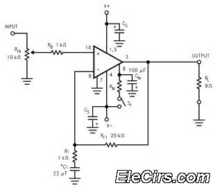
The LM3886 high-performance audio power amplifier circuit schematic is a crucial component in sound reproduction within audio systems. This audio power amplifier utilizes the LM3886 integrated circuit to enhance sound quality and output. The LM3886 is a high-performance audio power...
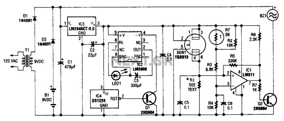
The gas sensor primarily consists of tin dioxide mounted on a ceramic substrate. The sensor's resistance changes based on the concentration of reducing gases present in the air. The depicted circuit is effective for detecting hazardous levels of combustible...
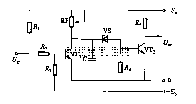
The circuit is a rechargeable short delay control for a conducting pipe, featuring two adjustment potentiometers (RP) that enable the delay time to be set from several hundred milliseconds to several seconds. The rechargeable short delay circuit is designed for...
Do you long for a beach holiday on a tropical island, but you don't have the necessary means? There is a solution: build the i-TRIXX surf simulator, put on your headphones, and escape from this mundane reality. Allow the...
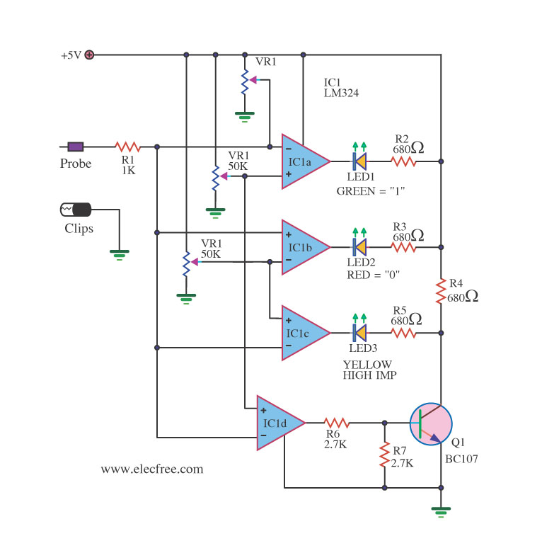
A logic probe is a useful tool for checking digital circuits. It functions similarly to a meter, which is employed to measure power in electrical circuits. A logic probe is an essential diagnostic instrument in digital electronics, designed to analyze...
The function of the sound level display circuit is to enhance the appearance of an amplifier circuit or a radio player. It provides an impressive visual representation of audio levels. The sound level display circuit serves as a visual indicator...