
remote control and Intruder detector
The described ultrasonic transmitter circuit operates on principles established in the mid-1970s, utilizing discrete components rather than integrated circuits (ICs). The circuit's primary function is to generate ultrasonic signals that can be used for remote control applications, typically in conjunction with a corresponding receiver circuit.
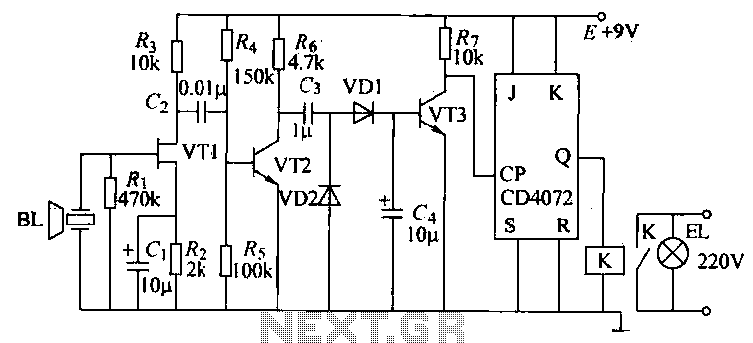
The transmitter circuit likely comprises a signal generator, which could be a simple astable multivibrator configuration using bipolar junction transistors (BJTs) or field-effect transistors (FETs) to produce a square wave signal. This square wave is then fed into a piezoelectric transducer, which converts the electrical signal into ultrasonic sound waves. The frequency of the generated signal is critical and is typically in the range of 20 kHz to 40 kHz, which is beyond the audible range for humans.
To enhance the performance and efficiency of the circuit, operational amplifiers (op-amps) could be integrated into the design. Op-amps can be utilized to amplify the output signal from the signal generator before it reaches the transducer, ensuring that the ultrasonic waves produced are strong enough to be effectively transmitted over the desired distance. Additionally, op-amps can be employed in filtering applications to eliminate any unwanted noise from the signal, thereby improving clarity and reliability.
The circuit is designed for single-channel operation, which limits its functionality compared to modern multi-channel systems. In the past, multi-channel ultrasonic chips were available, allowing for more complex communication setups. However, as ultrasonic technology has become less prevalent in commercial applications, many of these components are now considered obsolete, making the design of new systems more challenging.
In summary, the ultrasonic transmitter circuit described employs fundamental electronic principles and discrete components to generate ultrasonic signals for remote control applications. Its design can be enhanced with the inclusion of op-amps to improve signal strength and reduce noise, although its single-channel limitation reflects the technological constraints of its era.These ultrasonic circuits are all quite old: my notes date them at mid-70s so they don`t use ICs. Nevertheless there are several places where an op-amp would possibly simplify things. Despite their age I hope they are of interest: certainly basic principles don`t change. This transmitter is designed to work with the next circuit as a remote control transmitter/receiver. It is only a single channel and you could once get multi-channel chips for the whole job. However ultrasonics have fallen out of favour commercially so I think most of these chips are now obsolete. 🔗 External reference
Related Circuits

Diode D1 and resistor R1 provide VDD isolation during the programming of 24-pin devices. The jumper J3 must be shorted for 24-pin device programming and left open for 28-pin device programming. The following EEPROMs are pin-compatible with their EPROM...

The project demonstration has been successfully completed, with the only remaining task being the final project report due on June 15, which will be integrated with a conference paper. This update marks the last entry in the electronic notebook,...
The objective of this project is to create a controller-based model that counts the number of individuals entering a specific room and activates the lighting accordingly. A sensor will be utilized to determine the current number of persons present....
With the help of a simple ceramic piezoelectric detector, it is possible to assemble an interesting and useful impact sensor unit, which can be used to detect... An impact sensor unit utilizing a ceramic piezoelectric detector operates by converting mechanical...
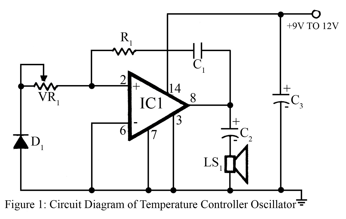
The output frequency or tone of this oscillator circuit varies with the temperature at which the input germanium diode is maintained. The reverse resistance of D1 ranges from 500 ohms to 10 k ohms when the temperature fluctuates between...
The T-40-16 and 555 ultrasonic transmitter circuit configuration consists of an ultrasonic transmitter T-40-16 and a 555 timer circuit. By adjusting the potentiometer RP, the oscillation frequency of the circuit can be changed. The output pulse frequency from the...