
remote control
The circuit operates effectively by utilizing infrared communication between the TV remote and the TSOP 1738 receiver. The TSOP 1738 is sensitive to IR signals modulated at 38 kHz, making it compatible with most TV remotes. The output from the TSOP is fed into a monostable multivibrator circuit formed by IC2. The monostable configuration ensures that each press of the remote produces a fixed duration pulse, which is crucial for reliable switching of the connected load.
The use of a flip-flop within the circuit provides a memory function, allowing the appliance to remain in its last state until the next signal is received. This design is particularly beneficial in applications where user convenience is paramount, enabling seamless control over appliances without the need for physical switches.
The relay used in the circuit should be selected based on the anticipated load. A relay with a coil voltage rating compatible with the circuit's supply voltage should be chosen, and the contact ratings should exceed the current requirements of the connected device to ensure safe operation. Additionally, a freewheeling diode (D1) is critical for protecting the circuit from back EMF generated by the relay coil when it is de-energized, enhancing the circuit's reliability and longevity.
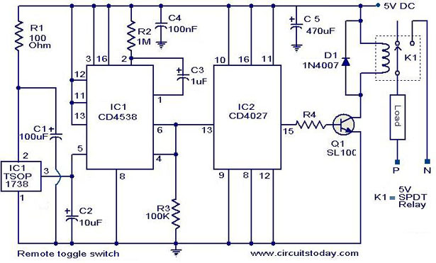
Overall, this circuit exemplifies a practical application of remote control technology in home automation, providing a user-friendly interface for controlling electrical appliances.In application level this circuit is similar to that of the circuit given previously. The only difference is in the approach. This circuit is designed by using another method. Using this circuit you can toggle any electrical appliance between ON and OFF states by using your TV remote. The only requirement is that your TV remote should be operating in the 38 KHz. The IC1 (TSOP 1738) is used to receive the infrared signals from the remote. When no IR signal from remote is falling on IC1, its output will be high. When the IR signal from the remote falls on the IC1, its output goes low. This triggers the IC2 which is wired as a monostable multivibrator. The output of the IC2 (pin6) goes high for a time of 1S (set by the values of R2 and C3. This triggers the flip flop (IC2) and its Q output (pin 15) goes high. This switches on the transistor, which activates the relay and the appliance connected via relay is switched ON. For the next press of remote the IC1 will be again triggered which in turn makes the IC2 to toggle its output to low state.
The load will be switched OFF. This cycle continues for each press of the remote. The pin 6 and pin 4 of IC1 are shorted to avoid false triggering. The diode D1 can be used as a freewheeling diode. The current capacity of relay determines the load circuit can switch. Use a high amperage(`10A or above) relay for driving large loads like motor, heater etc. 🔗 External reference
Related Circuits
Sometimes, for a variety of reasons, it would be nice to vary the width of the sound stage when listening to stereo recordings. Although technically this is anything but hi-fi, it is a useful addition to PC speakers, or...
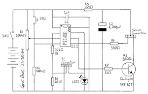
This project involves creating a programmable camera controller using basic hand tools and a digital camera. By utilizing components that are commonly found at home, the overall costs can be minimized. A servomotor can be repurposed from a radio-controlled...
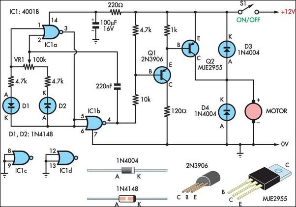
Two simple 12V DC motor speed controllers can be constructed for a minimal cost. These controllers take advantage of the principle that the rotational speed of a DC motor is directly proportional to the average value of its supply...
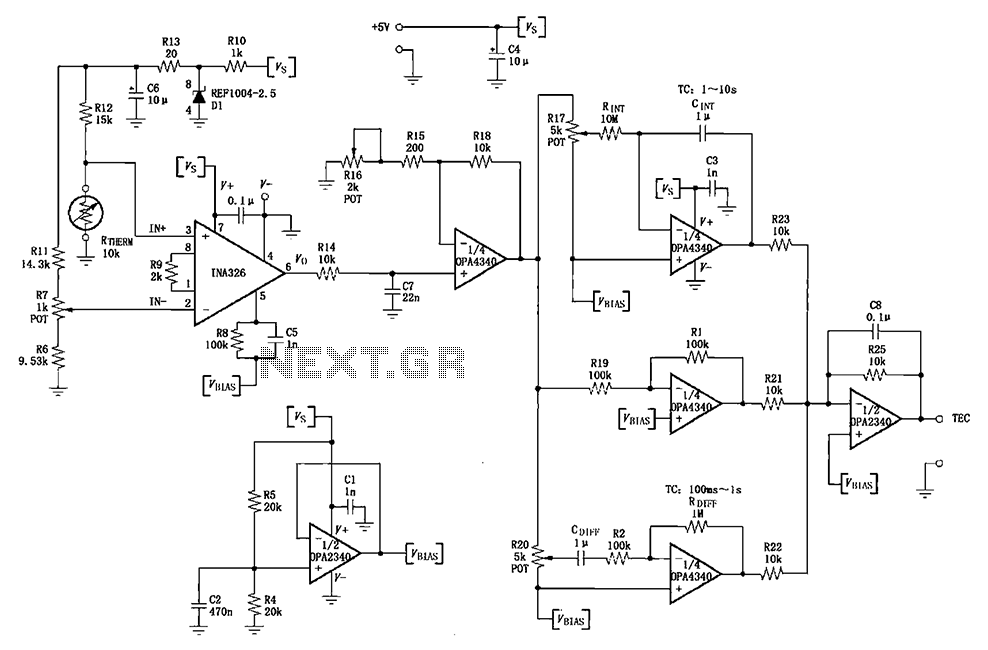
The INA326/327 forms a single power PID (proportional-integral-derivative) controller as illustrated in the temperature control loop. This circuit is primarily designed for temperature measurement and control. A thermistor, designated as RTHERM, detects temperature changes and converts them into an...
Most stroboscopes designed for commercial use, such as light effects, theatrical lighting, and DJ lights, are equipped with external trigger connectors on the back. These trigger inputs typically utilize 6.3 mm jacks or XLR connectors. Occasionally, there is one...
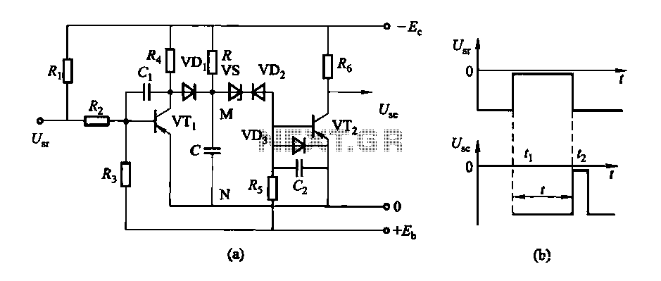
The circuit features a delay action with an instantaneous reset control mechanism. It is categorized into three types: a conducting pipe rechargeable delay circuit, a tube cut-off control rechargeable delay circuit, and a discharge-type delay circuit. In the conducting...