
Strobo controller
by just connecting the first stroboscope to controller and wiring next strobocope to the output of he first stroboscope etc. This stroboscope controller is a simle adjustable multivibrator which gan easily generate frequencies at frequency range 1.
15 Hz and output suitable control signal pulse to trigger the stroboscope. The circuit diagram is a little bit modified standard 555 based astable oscillator circuit with some extra electronics added to the output side. The capacitor C3 is charged through R1 and D2. When capacitor charges the 555 timer outputs high stage (+8V output voltage). When the capacitor is fully charged the 555 timer starts to discarge it through R2 and R3. The resistance of R2 and R3 ddetermines the discharge time (and so the frequency of pulses, typically between 1 and 15 Hz).
The output of the 555 timer can be connected to the output circuitry using SW2. The output circuitry has a LED D4 which shows the signal output state (flashing pulses). Normally the positive pulses get to the output connector through D3 and R6. Single manual flash can be accomplished by pressing SW1 which connects the circuit power to the output pin (also R6). R6 is on the output to limit the current to safe values in situation where there is a short circuit in the control cable or in the connectors.
to 7808 regulator with C1 and C2 make a well regulated 8V voltage from the input voltage. D1 is in the power input to protect this circuit against wrong polarity input voltage. C1 22 uF 35V electrolytic C2 220 nF C3 22 uF C4 22 nF D1 1N4007 D2, D3 1N4148 D4 RED LED (high intensity model preferred) R1 2. 2 kohm R2 47 kohm potentiometer (lin) R3 4. 7 kohm trimmer R4 470 ohm R5 470 ohm R6 100 ohm 1W SW1 Pushbutton (push turns it on) SW2 Changeover switch U1 LM555, NE555 or similar U2 7808 regulator IC Because the strobo controller is expected to face all kind of mechahical shocks in it`s operating environment it is recommended to construct it mechanically well.
Use a good quality project case which protects the circuit nicely and where you can fit the circuit board so that it can take mechanical shocks without damage (for example stand dropping from a table). In some apllications a quite heavy metal box with rubber feets might be a very good because it does not drop easily from the table because of the weight of the strobo control cable.
Use a good quality potentiometer and install a good knob carefully so that mechanical shock to the knob can`t easily damage the potentiometer. Use switch and button which can take hard use without damage. Cheap buttons can break up easily which is not very nice when you need the strobo controller. Better to be safe than sorry. The 7808 regulator does not need a heatsink because the current taken by this circuit is quite small.
There circuit itself can be constructed to a small circuit board (you have to design your own) or to a small piece of veroboard. Use a good quality connector for the power input because your circuit is expected to take hard use. Use 6. 3 mm jack for the signal output, because this connector can take some hard use and it is widely used in this kind of applications.
When you use stadard connector you can also use standard audio cables between the controller and the stroboscope. I built my own circuit to a small plastic box where I fitted the DC power connector, 6. 3 mm output jack, switches and potentionmeter. The picture below is as taken from my protoype: When you have the circuit ready and working then you have to set up the maximum frequency limit on this circuit.
It is 🔗 External reference
Related Circuits
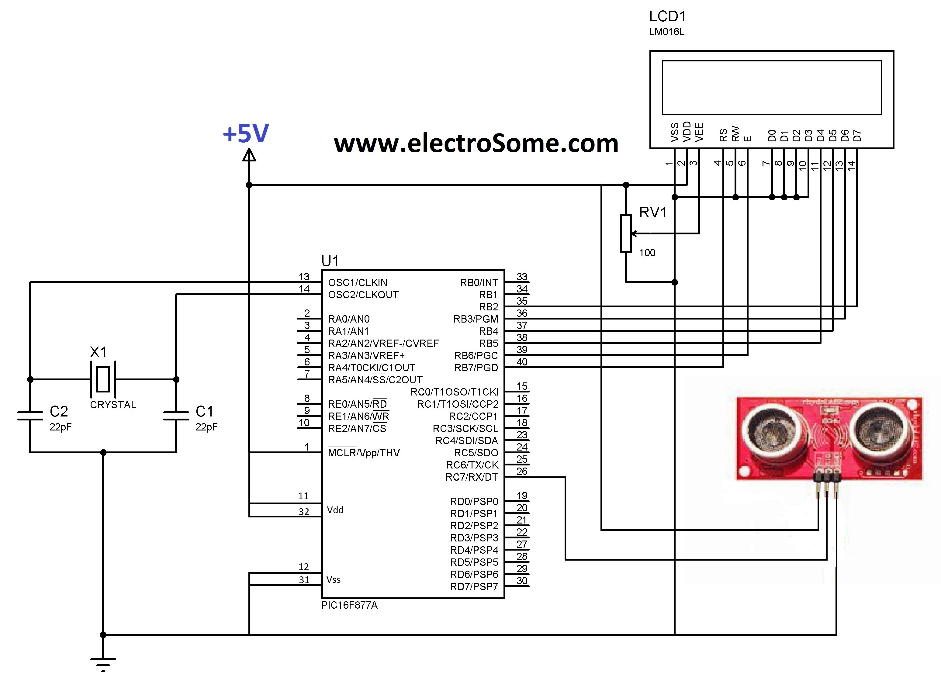
LCD initializations in 8051 C programming involve understanding the logic behind serial communication, including the duration of SIG pulse transmission and the necessary delays. These statements inform the compiler that a 16x2 LCD is connected to the defined pins...

Microsemi's LX6512 is a cost-effective, Direct Drive CCFL (Cold Cathode Fluorescent Lamp) controller. The integrated controller is optimized to drive CCFLs (Cold Cathode Fluorescent Lamps). The Microsemi LX6512 is designed to provide efficient and reliable operation for driving Cold Cathode...
The Arduino microcontroller board can supply a current of 40mA from its output connections, with digital outputs fixed at 5V for "ON" and 0V for "OFF." This current is suitable for LEDs, but devices like motors, solenoids, and high-brightness...
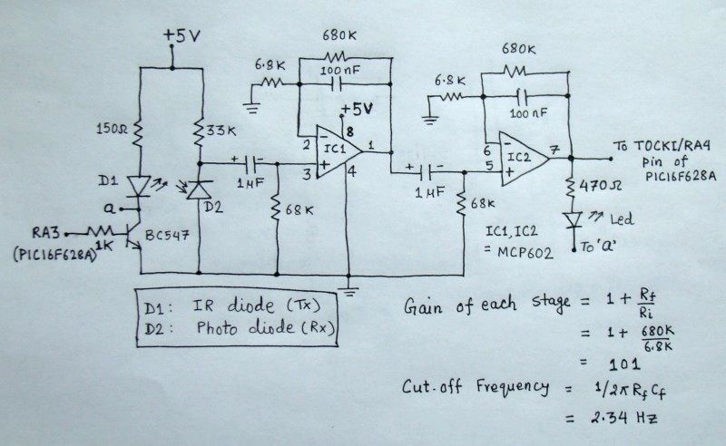
The reflected infrared (IR) signal detected by the photodiode is sent to a signal conditioning circuit, which filters out unwanted signals and amplifies the desired output. The circuit begins with a photodiode that captures the reflected IR signals. The photodiode...
This standalone digital thermometer regulates the temperature of a device based on its requirements. It displays the temperature on four 7-segment displays, with a range from 55 to +125 °C. The core of the circuit is the AT89S52 microcontroller,...
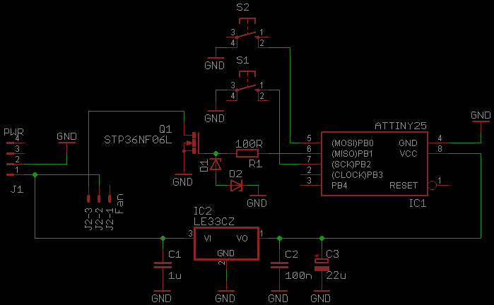
This document serves as a continuation of the previous work on PWM controllers utilizing 555 timers. The new design incorporates microcontrollers and MOSFETs in place of the 555 integrated circuits and transistors. Two versions have been developed: one equipped...
Warning: include(partials/cookie-banner.php): Failed to open stream: Permission denied in /var/www/html/nextgr/view-circuit.php on line 713
Warning: include(): Failed opening 'partials/cookie-banner.php' for inclusion (include_path='.:/usr/share/php') in /var/www/html/nextgr/view-circuit.php on line 713