
Stereo Width Controllers
To implement a circuit that allows for the adjustment of the sound stage width in stereo audio systems, a simple variable resistor (potentiometer) can be utilized in conjunction with an operational amplifier (op-amp) configuration. The primary objective is to manipulate the audio signal levels of the left and right channels to create a perceived change in sound stage width.
The circuit can be designed as follows:
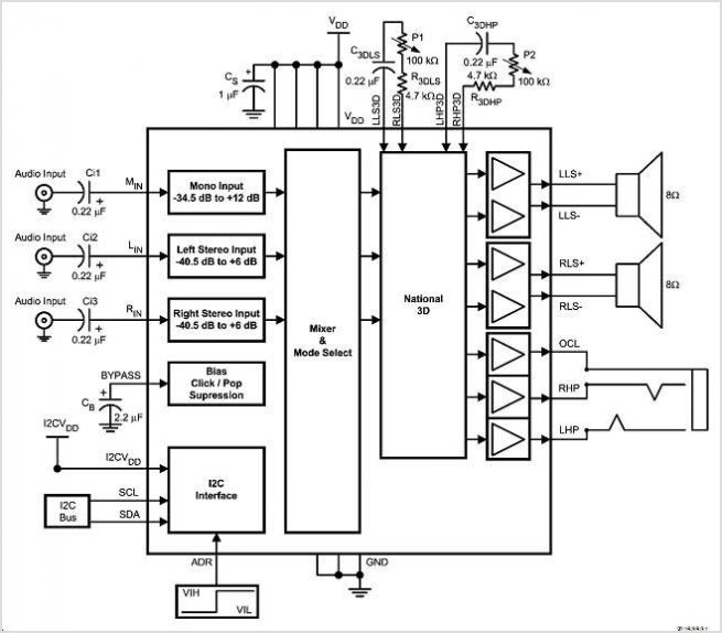
1. **Input Stage**: The audio input from the stereo source (e.g., PC or music center) is fed into the circuit. Each channel (left and right) should be treated separately to maintain stereo integrity.
2. **Potentiometer Configuration**: A dual-gang potentiometer is connected to each audio channel. The wiper of the potentiometer controls the level of the audio signal that is fed into the op-amps. By adjusting the potentiometer, the user can increase or decrease the gain of one channel relative to the other, effectively altering the perceived width of the sound stage.
3. **Operational Amplifiers**: Two op-amps are used, one for each channel. The op-amps are configured in a non-inverting amplifier setup. The gain of each op-amp can be set using feedback resistors, allowing for fine-tuning of the audio signal level. The output of each op-amp feeds into the respective left and right audio outputs.
4. **Output Stage**: The outputs from the op-amps are connected to the speakers. The adjusted signals will create the desired effect of widening or narrowing the sound stage based on the potentiometer settings.
5. **Power Supply**: The op-amps require a dual power supply (positive and negative) to operate effectively. A standard ±15V power supply can be utilized, ensuring that the op-amps function within their specified voltage range.
6. **Additional Features**: For enhanced functionality, a bypass switch can be integrated to allow the user to toggle between the modified sound stage effect and a direct connection to the audio source, ensuring that the original sound quality can be preserved when desired.
This circuit can be implemented on a PCB or a breadboard for prototyping, and it provides a practical solution for users who wish to customize their listening experience without compromising overall sound fidelity.Sometimes, for a variety of reasons, it would be nice to vary the width of the `sound stage` when listening to stereo recordings. Although technically this is anything but hi-fi, it is a useful addition to PC speakers, or even for the music centre in the listening room.
🔗 External reference
Related Circuits
The LMC568 is an amplitude-linear phase-locked loop that includes a linear voltage-controlled oscillator (VCO), fully balanced phase detectors, and a carrier detect output. It utilizes LMCMOS technology to achieve high performance while maintaining low power consumption. The VCO features...
A high-quality FM stereo transmitter circuit schematic utilizing the BA1404 FM transmitter integrated circuit (IC). This circuit is straightforward to assemble, requiring only a few external components. The FM stereo transmitter circuit based on the BA1404 IC is designed to...
To understand how the 74AC14 PWM circuit functions, it is essential to focus on the schematic section that includes the trimpot, diodes, capacitor, and the first inverter logic gate. Initially, when power is applied to the circuit, the capacitor...
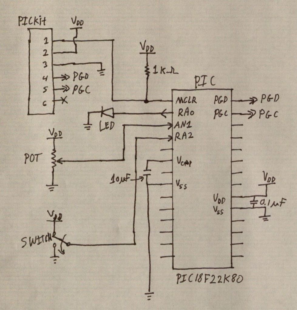
PIC microcontrollers are a highly useful and versatile component for various electronic projects. They are affordable and readily available. PIC microcontrollers are embedded systems that serve as the central control unit in a wide range of electronic applications. Their architecture...
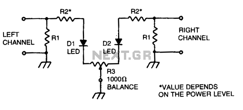
This circuit enables the adjustment of the gain for two stereo channels to achieve equal levels. The signal across the load resistors for both channels is sampled using resistors R2, with their values depending on the power level. For...
Powering up twin digital Sony DSC-V1 cameras simultaneously can achieve remarkable synchronization within milliseconds. This is accomplished through the use of dual Sony wired remotes that short the ACC port LANC signal conductor to the ACC port ground. Further...