
Remote Control Circuit Using KT3170
The operation of the circuit begins once a call is established (after the ring-back tone is heard), at which point the user dials 0 in DTMF mode. The IC1 decodes this as 1010, which is then demultiplexed by IC2, resulting in output O10 (at pin 11) of IC2 (74154). The active low output from IC2, after being inverted by an inverter gate from IC3 (CD4049), becomes logic 1. This logic level is used to toggle flip-flop-1 (F/F-1), thereby energizing relay RL1. Relay RL1 features two changeover contacts: RL1(a) and RL1(b). When RL1(a) is energized, it creates a 220-ohm loop across the telephone line, while RL1(b) injects a 10kHz tone onto the line, signaling to the caller that appliance mode has been selected. The 220-ohm loop disconnects the ringer from the telephone line within the exchange, allowing for appliance operation mode.
If digit 0 is not dialed in DTMF mode after the call is established, the ringing continues, and the telephone remains available for normal conversations. After entering appliance mode, dialing digit 1 is decoded by IC1, producing output 0001. This BCD code is then demultiplexed by the 4-to-16 line demultiplexer IC2, and the corresponding output, after inversion by a CD4049 inverter gate, transitions to logic 1. This pulse toggles the associated flip-flop to an alternate state, and the output of the flip-flop is used to control relay RL2, which can switch the connected appliance on or off. Other appliances can similarly be controlled by dialing different digits.
Once the switching operations are completed, it is necessary to remove the 220-ohm loop resistance and the 10kHz tone from the telephone line. This is accomplished by dialing digit 0 again in DTMF mode, which toggles flip-flop-1 to deactivate relay RL1, terminating the loop on the line and disconnecting the 10kHz tone. The telephone line is then restored for normal call reception. This circuit should be connected in parallel with the telephone instrument to function correctly.This circuit is which enables switching on` and off` of appliances through telephone lines. It can be used to switch appliances from any distance, overcoming the limited range of infrared and radio remote controls. The circuit described here can be used to switch up to nine appliances (corresponding to the digits 1 through 9 of the telephone key-p
ad). The DTMF signals on telephone instrument are used as control signals. The digit 0` in DTMF mode is used to toggle between the appliance mode and normal telephone operation mode. Thus the telephone can be used to switch on or switch off the appliances also while being used for normal conversation.
The circuit uses IC KT3170 (DTMF-to-BCD converter), 74154 (4-to-16-line demulti-plexer), and five CD4013 (D flip-flop) ICs. The working of the circuit is as follows. Once a call is established (after hearing ring-back tone), dial 0` in DTMF mode. IC1 decodes this as 1010, ` which is further demulti-plexed by IC2 as output O10 (at pin 11) of IC2 (74154).
The active low output of IC2, after inversion by an inverter gate of IC3 (CD4049), becomes logic 1. This is used to toggle flip-flop-1 (F/F-1) and relay RL1 is energized. Relay RL1 has two changeover contacts, RL1(a) and RL1(b). The energized RL1(a) contacts provide a 220-ohm loop across the telephone line while RL1(b) contacts inject a 10kHz tone on the line, which indicates to the caller that appliance mode has been selected. The 220-ohm loop on telephone line disconnects the ringer from the telephone line in the exchange. The line is now connected for appliance mode of operation. If digit 0` is not dialed (in DTMF) after establishing the call, the ring continues and the telephone can be used for normal conversation.
After selection of the appliance mode of operation, if digit 1` is dialed, it is decoded by IC1 and its output is 0001`. This BCD code is then demulti-plexed by 4-to-16-line demulti-plexer IC2 whose corresponding output, after inversion by a CD4049 inverter gate, goes to logic 1 state.
This pulse toggles the corresponding flip-flop to alternate state. The flip-flop output is used to drive a relay (RL2) which can switch on or switch off the appliance connected through its contacts. By dialing other digits in a similar way, other appliances can also be switched on` or off`. Once the switching operation is over, the 220-ohm loop resistance and 10kHz tone needs to be removed from the telephone line.
To achieve this, digit 0` (in DTMF mode) is dialed again to toggle flip-flop-1 to de-energize relay RL1, which terminates the loop on line and the 10kHz tone is also disconnected. The telephone line is thus again set free to receive normal calls. This circuit is to be connected in parallel to the telephone instrument 🔗 External reference
Related Circuits
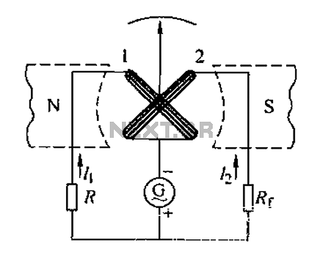
Also known as a megger insulation resistance meter, this device measures resistance at the megohm level. It is primarily used to assess the insulation resistance of motors, electrical circuits, and equipment. Additionally, it helps determine whether there is circuit...
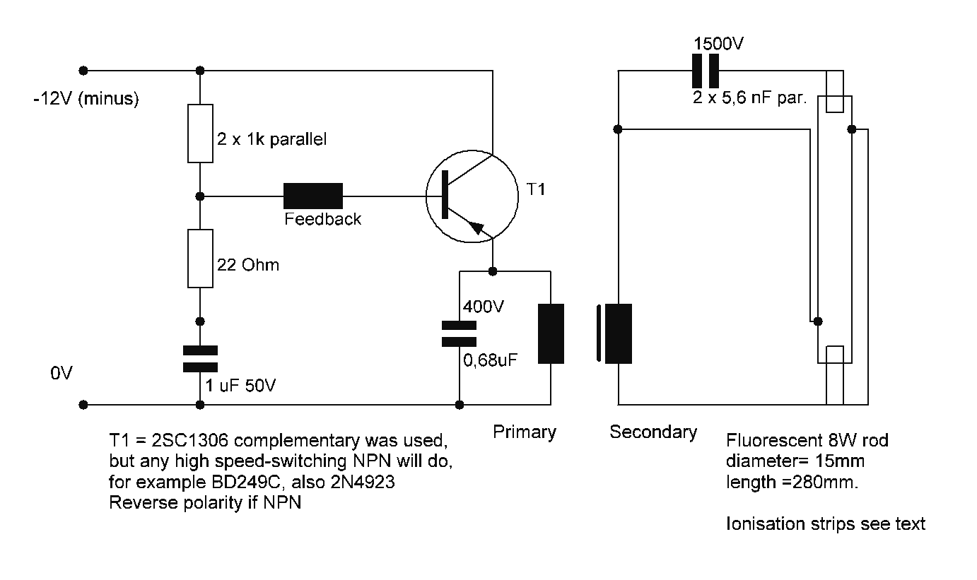
Starting a fluorescent lamp on an inverter can be challenging due to the trade-offs involved in achieving optimal operating efficiency with 12V drivers. Fluorescent lamps require a specific starting voltage to ionize the gas within the tube and initiate the...
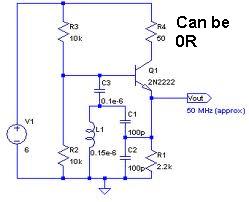
An oscillator circuit capable of generating a high-quality sine wave with a frequency of at least 500 MHz, intended for RFID applications. There have been attempts to utilize a class E oscillator, but the design has not yet been...
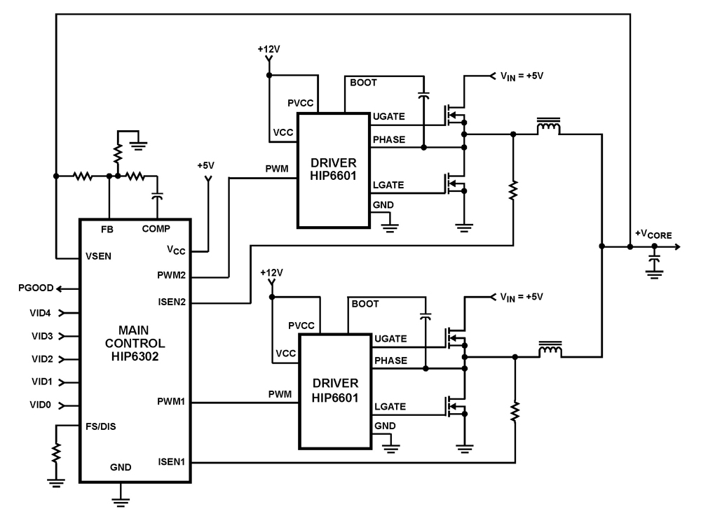
The HIP6302 Multiphase PWM control IC, along with its companion gate drivers (HIP6601, HIP6602, or HIP6603) and Intersil MOSFETs, delivers a precise voltage regulation system for advanced microprocessors. Multiphase power conversion represents a significant advancement over traditional single-phase converter...
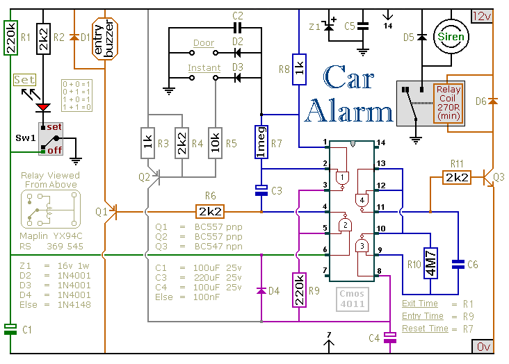
This circuit is designed to secure a vehicle at a low cost if constructed independently, making it more affordable than purchasing a commercial car alarm system. The alarm is activated by opening switch Sw1, which can be any small...
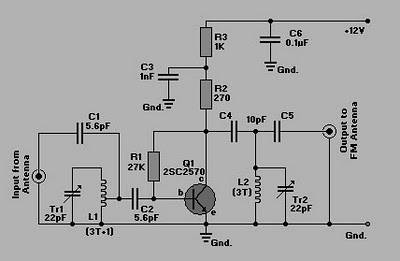
This is a simple circuit of an FM booster designed to enhance the reception of programs from distant FM stations. The amplifier effectively captures signals from far-off FM stations. The configuration is set up as a common-emitter tuned RF...