
Remote control fan regulator
To successfully implement this design, a foundational understanding of electronics is beneficial. Key areas of knowledge include direct current (DC) and alternating current (AC) theory, transistor operation, operational amplifiers, and digital circuit design. It is recommended for individuals with limited experience in electronics to pursue additional training or coursework to strengthen their skills before attempting to construct such a project. A practical approach to learning could involve building a variable DC voltage power supply, which would serve as a useful tool for various projects. Utilizing simulation software can also aid in testing circuit designs before physical assembly, allowing for a smoother transition from theory to practice. This project, while basic in concept, provides an excellent opportunity for hands-on experience in electronics design and implementation.IR`s or bluetooth will work for short range, dedicated radio for longer range. Depending on what you choose it will alter your design. Since a fan only has a few settings. low, medium, high and off. what about using a DTMF chip to send and recieve a signal I could see a system where you have 4 buttons on the remote. Press a button and a DTMF signal get passed through an amp to an antennae. (or IR LED) On the reciever end, the recieving DTMF chip enterprets the signal, and logic gates turn on or off one of 4 relays that applies the appropriate amount of current to the fan for that setting. Actually i want to construct a remote by which i can operate rpm speed & on/off of the ac fan which I use in daily life(i.
e. a normal fan in ac). It enables the user to operate a fan regulator from approximately 10 meters away. The remote transmits a tone using an infrared light-emitting diode. This tone is decoded by a receiver, since the receiver only switches when the tone is received. With two of the dual tone/ multiple frequency transceiver chips (like the one I posted) You could use one for the remote, and one for the receiver. Since most fans (and I assume yours does too) have 4 settings, the 4 bit data bus would be easy to use.
Just have 4 buttons that each apply power to each one of the pins of the input so that: Then connect the output of the DTMF chip to a IR LED (or throw an op amp in between, if the chip output doesn`t have enough power to directly drive the LED) On the receiver end, connect a photocell to the input of the DTMF reciever (again with an OP amp in between if needed) The 4 output pins would connect to 4 small relays (via a gate to keep them on) that would apply AC power to the fan through the fan`s existing rotary switch. Just get rid of the roter, and directly connect to each one of the terminals on the fans switch. Super simple circuit that I described. The two MT8880C`s do the transmitting and recieving. You just need to connect an IR LED on the output of the transmitter, and a photocell to the input of reciever.
How much experience do you have with electronics I am 1 year 6 months experience, in this i can build the circuit & solder the circuit, but I have not much experience in electronics because I have not done any training on micro controller or embedded system. Now I am doing some projects so that I can get some practical knowledge & I will do the training on next semester.
That is why I am doing this little project. I tried to come up with the most basic design I could. You will probably will need some classes on basic DC and AC theory, transitors, op amps, and digital circuits before you would be able actually design and construct a circuit like this. I went to a 2 year electronics school, that was broken up into 8 quarters. I was in 5th quarter before I had everything I needed to build something like this. This allows you to plug in components and connect them together to test the circuit before you finalize it.
Another is a variable DC voltage power supply. Now this is something you could build for yourself, and would be useful with other projects. Here`s an example of what it would look like: If I were you, I would put the remote control fan project on the back burner, until you get a little training in school. I would be happy to help you with the design and construction of a power supply. This would be something that you could use to help you learn. A couple of other things you might consider 🔗 External reference
Related Circuits
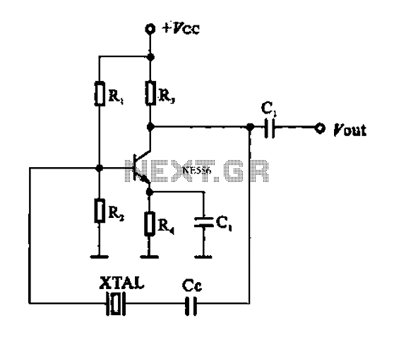
A series resonant circuit utilizing a crystal oscillator is illustrated. The crystal impedance reaches a minimum value at the series resonance frequency, resulting in a significant feedback amount. The crystal tuning capacitor (Cc) can slightly adjust the resonance frequency...
This compact circuit is designed to control model railway turnouts that operate using AC voltages. A control signal within the range of 5 to 12 volts can be utilized. The turnout coils are activated by triacs. Variations in the...
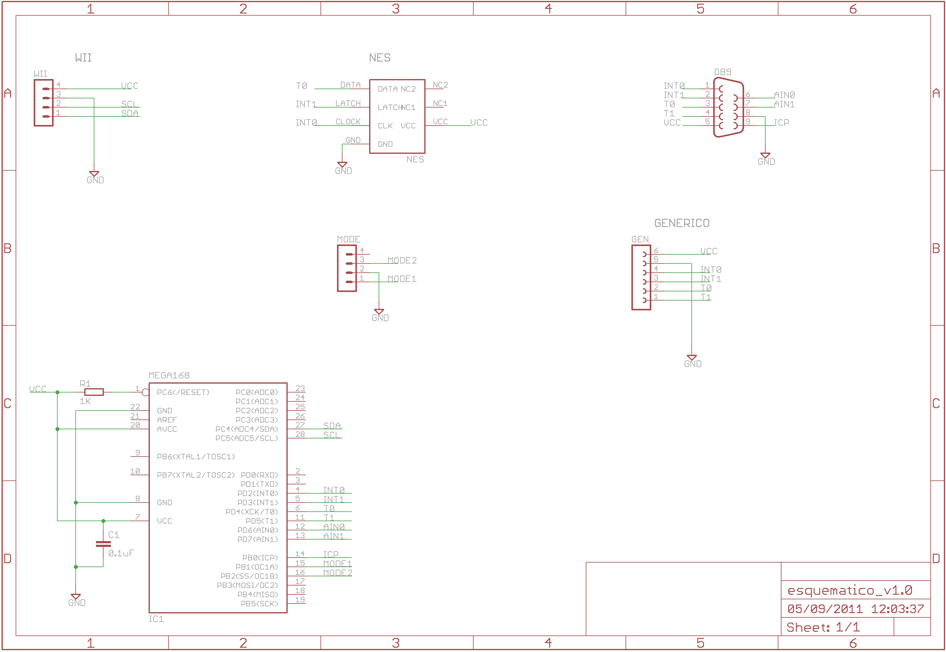
The Wii RetroPad Adapter allows the use of PlayStation 2, Genesis, NES, and SNES controllers with the Wii console. The Wii RetroPad Adapter is a versatile accessory designed to enhance the gaming experience by enabling compatibility between multiple classic gaming...
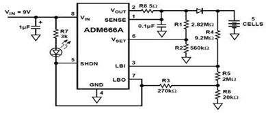
The ADM666A application note provides a detailed explanation of a low-cost battery charger circuit, including maximum output voltage, charge termination voltage calculation, battery voltage level monitoring, and circuit efficiency optimization. The ADM666A utilizes an NPN transistor and a P-channel...
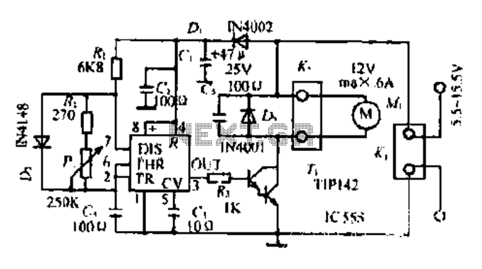
Most governors utilize pulse width modulation (PWM) and pulse position modulation (PPM) in their circuits. The 555 timer is commonly used in these applications. The pulse width is typically fixed at 0.5 milliseconds, which is essential for the functioning...
The MAXQ3210 is a powerful RISC microcontroller. This device has features and capabilities that make it suitable for battery-powered applications that require detection. The MAXQ3210 microcontroller is designed with a focus on low power consumption and efficiency, making it particularly...