
model railway turnout control
The circuit operates effectively by utilizing a combination of triacs and a buffering stage to control the turnout coils of model railways. The triacs, specifically chosen for their low gate current requirements, allow for efficient operation without excessive power consumption. The buffer stage, which is critical for ensuring that the triacs receive adequate gate current, consists of two transistors that amplify the control signal.
When the control signal is activated, capacitor C1 momentarily charges, allowing current to flow to the gate of T3. This activates the triac, which then powers the turnout coil. The design is such that once C1 is charged, the gate current is cut off, resulting in the triac turning off after a predetermined time. This time can be adjusted by varying the capacitance of C1, allowing for flexibility based on the specific requirements of the model railway system.
The circuit also incorporates diodes D1 and D2 to ensure proper current flow direction and to protect the components from potential damage due to reverse currents. By utilizing both positive and negative gate triggering, the circuit can efficiently control two different turnout coils with a single control signal, enhancing its utility in model railway applications.
Overall, the described circuit provides a robust solution for controlling model railway turnouts with AC voltages, allowing for precise and reliable operation tailored to user preferences through component adjustments.This small circuit can be used to control model railway turnouts operated by AC voltages. A logic level in the range of 5 12 V can be used as the control signal. The coils of the turnout are switched using triacs. Changes in the logic level of the input signal are passed on by the buffer stage built around T1 and T2. The buffer stage is included to boost the current available at the gates of the triacs. If the input goes high, this positive change is passed through via C1. That causes a positive current to flow through D2 (D2 is reverse biased) to the gate of T3. That triac switches on, and power is applied to the turnout coil. This situation persists until C1 is fully charged. No more current flows after that, so the triac does not receive any gate current and switches off. If the input is set low, a negative current flows briefly via C1. It can flow through D2, but not through D1. T4 is switched on now, and the other turnout coil is energised. This circuit takes advantage of the fact that triacs can be triggered by negative as well as positive gate currents. If the turnout coils are energised for too long, you should reduce the value of C1. If they are not energised long enough, increase the value of C1. The TIC206D can handle several ampG¨res, so it can easily drive just about any type of turnout coil. You can also use a different type of triac if you wish. However, bear in mind that the TIC206 requires only 5 mA of gate current, while most triacs want 50 mA.
That will cause the switching times to become quite short, so it may be necessary to reduce the value of R1. 🔗 External reference
Related Circuits
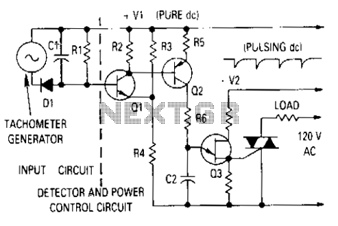
The generator output is rectified, filtered, and applied between the positive supply voltage and the base of the detector transistor. This configuration provides a negative voltage that reduces the base voltage as the speed increases. During normal operation, if...
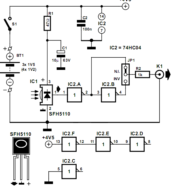
Many audio systems consist of separate units, and due to economic reasons, only the amplifier is equipped with a remote control receiver module. In audio system designs where components are split into separate units, it is common for only the...

The ATR0981 is a monolithic integrated circuit (IC) produced using Atmel's advanced SiGe technology. This IC serves as a transmit and receive front-end solution, specifically designed for operation within a frequency range of 300 MHz to 500 MHz. It...
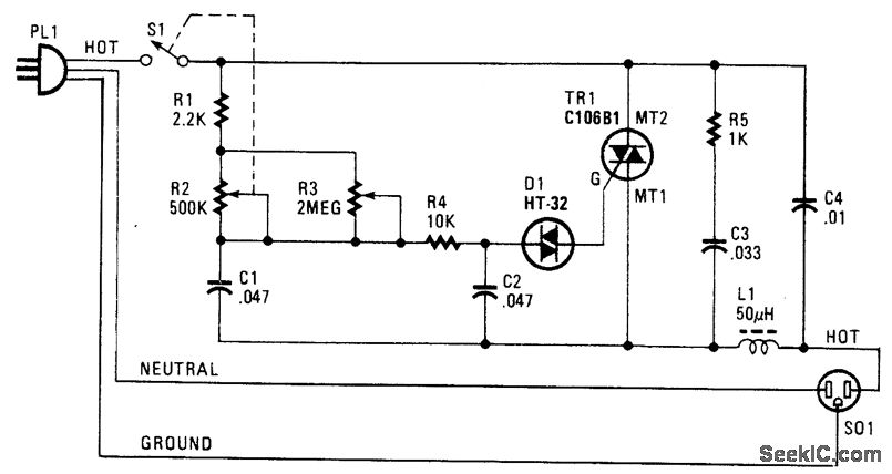
The following circuit illustrates a Phase Controlled Triac (HT-32) Circuit Diagram. Features include a simple circuit design, and bilateral triggering diacs provide a... The Phase Controlled Triac circuit, utilizing the HT-32 component, is designed for applications requiring precise control of...
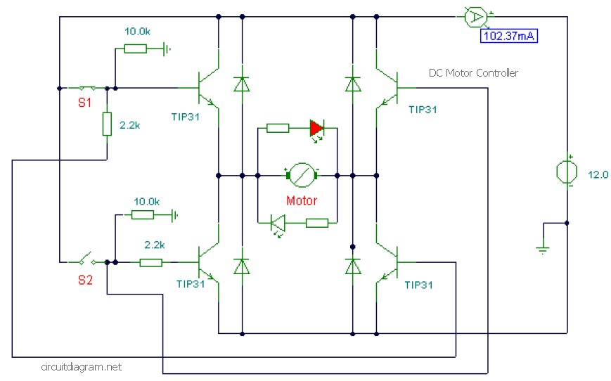
This is a DC motor controller circuit built using the TIP31 transistor based on the H-Bridge concept. The switches S1 and S2 are normally open, push-to-close buttons. The LED serves to indicate the direction of motor rotation and any...
This information pertains to a dosing pump control circuit that utilizes the LM317 integrated circuit (IC). The circuit operates with a power supply of 24V DC and is capable of adjusting the output voltage to 1.25V. The LM317 is a...