
300-350W Lighting Control
The lighting control circuit designed for 300-350W applications is intended to provide a reliable and efficient means of controlling lighting systems in residential or commercial environments. The circuit operates at a standard voltage of 120V AC, making it suitable for use in regions with this voltage specification.
The schematic typically includes a few key components: a power source, a control switch, a relay or triac for switching, and load elements such as lamps or LED fixtures. The power source connects to the control switch, which allows the user to turn the lighting on or off as desired. When the switch is activated, it sends a signal to the relay or triac, which acts as an electronic switch to control the flow of current to the load.
The use of a relay is common in such circuits due to its ability to handle high currents safely while providing electrical isolation between the control circuit and the high-power load. Alternatively, a triac can be used for more advanced control, such as dimming capabilities, allowing for variable brightness of the connected lighting fixtures.
The components selected for this circuit should be rated appropriately for the expected load. For example, the relay should have a current rating above the maximum load current, and the control switch should be rated for 120V AC operation. Additionally, proper fusing or circuit protection should be included to prevent damage from overload conditions.
Overall, this lighting control circuit is designed to be cost-effective and straightforward, making it accessible for DIY enthusiasts and suitable for various lighting applications. Proper attention to component ratings and circuit design will ensure reliable performance and safety in operation.This circuit shows about 300-350W Lighting Control Circuit Diagram . Features: Cheap to build, Simple circuit, 120V AC voltages. Component: .. 🔗 External reference
Related Circuits
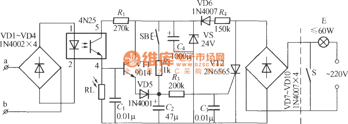
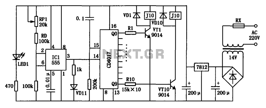
The diagram illustrates an automatic lighting control circuit activated by a telephone. At night, when the telephone rings or the user picks up the receiver, the light turns on. If the telephone stops ringing (when no one is listening)...
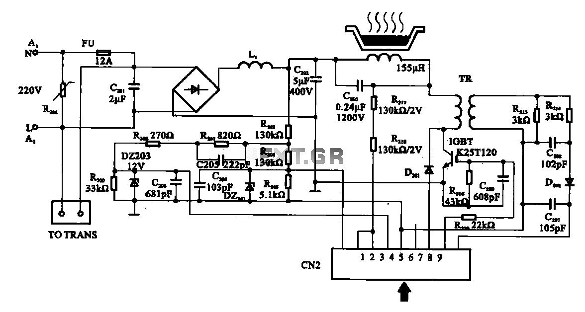
Cooker detection control circuit. The control circuit is designed for testing cookers. The inductance coil disc lesion typically measures around 150 µH. The stove plate coil and capacitor resonate with device C203. When resonating, the voltage generated across C203...
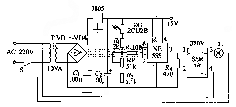
The NE555 time base circuit with an AC solid-state relay (SSR) can function as an automatic light switch circuit. The circuit diagram illustrates that during the day, the incandescent light is turned off due to the influence of the...
As summer approaches, many individuals focus on staying cool during hot days. For some, this means turning on the air conditioner and enjoying a cold beverage. However, it is essential to consider how to maintain the temperature of radio...

The anti-theft system includes two frequency sirens connected to the vehicle's immobilizer system. In the laboratory simulation model, the changes in operating modes, siren activation, and fuel supply cut-off are indicated by the illumination of LEDs and communicated to...
Modern exhibitions utilize extensive sound, light, and electrical technologies for advertising, promotion, and propaganda. This involves various electrical diagrams and control models. Commonly used is an automatic program circuit with pre-recorded commentary, which requires synchronization of two mating times....