
RF field strength meter circuit

A radio frequency (RF) field strength meter is a specialized device used to measure the strength of electromagnetic fields generated by RF signals. This instrument is essential for amateur radio operators and hobbyists involved in radio-controlled models, as it provides critical feedback on signal quality and strength.
The RF field strength meter typically consists of an antenna, a signal processing unit, and a display module. The antenna captures the RF signals from the environment, converting them into electrical signals. The signal processing unit amplifies and filters these signals to eliminate noise and enhance clarity. The processed signals are then displayed on an analog or digital readout, allowing users to assess the strength of the RF field in real-time.
Key features of a reliable RF field strength meter include a wide frequency range to accommodate various RF applications, high sensitivity to detect weak signals, and a robust design to withstand outdoor conditions. Additionally, some models may offer features such as data logging, frequency scanning, and the ability to interface with computers for detailed analysis.
Proper calibration of the RF field strength meter is crucial for accurate measurements. Regular maintenance and testing against known reference signals ensure that the device remains reliable over time. Understanding how to interpret the readings from the meter is also vital for effective use, as it can inform adjustments to antenna positioning, transmitter power levels, and overall system performance in both amateur radio setups and radio-controlled model operations.A sensitive and reliable rf field strength meter is an invaluable instrument in amateur radio and in radio controlled model area. A field strength meter is. 🔗 External reference
Related Circuits
The application that we propose is a simple filter that limits the acoustic region (20-20000Hz) to the region 20-100Hz. With the manufacture proposed, an active filter can be created to drive a loudspeaker for very low frequencies. This allows...
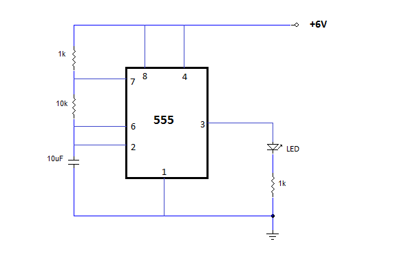
The NE555 is one of the most commonly used timer integrated circuits (ICs). It is a monolithic timing circuit capable of producing accurate and highly stable time delays or oscillations. Similar to general-purpose operational amplifiers, it is reliable, easy...
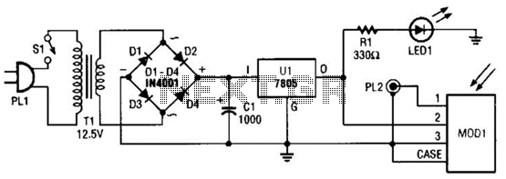
A schematic diagram for the remote analyzer is presented. The circuit is powered by a simple 5-V supply, which includes components such as PL1, SI, Tl, a bridge rectifier formed by diodes D1 through D4, capacitor CI, and a...
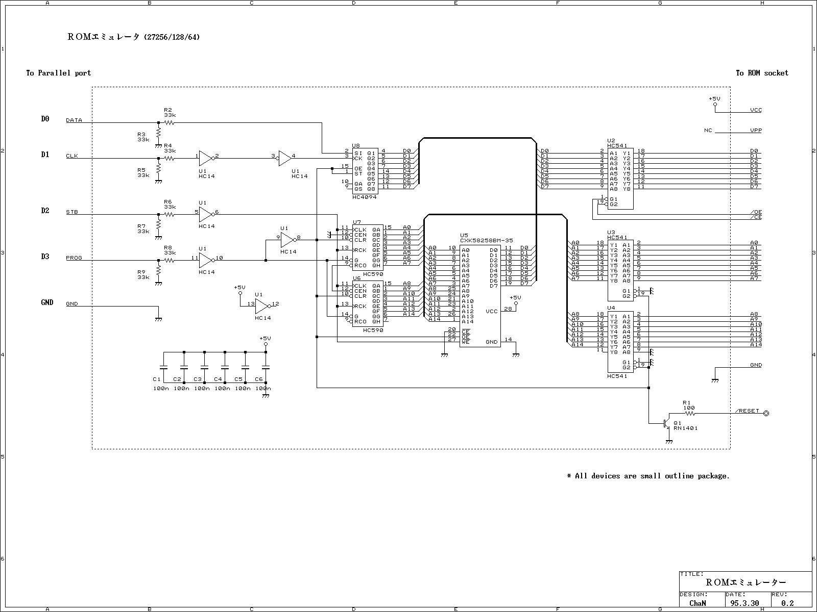
This ROM emulator improves the easiness to build/use it by reducing down its function which can be used as a ROM emulator. The kind of the ROM types to be emulated are 2764, 27128, and 27256. The debugging capability...
Many friends have requested an automatic on/off LED circuit or an LED flashing circuit. This post presents an astable multivibrator circuit designed for LED flashing. It is a simple astable multivibrator circuit utilizing two LEDs (specifically red LEDs) and...

The modification of the differential circuit is illustrated. In Figure A1, an integrator is depicted, and the output is presented. The circuit modification involves integrating the differential circuit with an integrator component, which plays a crucial role in signal processing...