
Electrical Appliance Time Controller
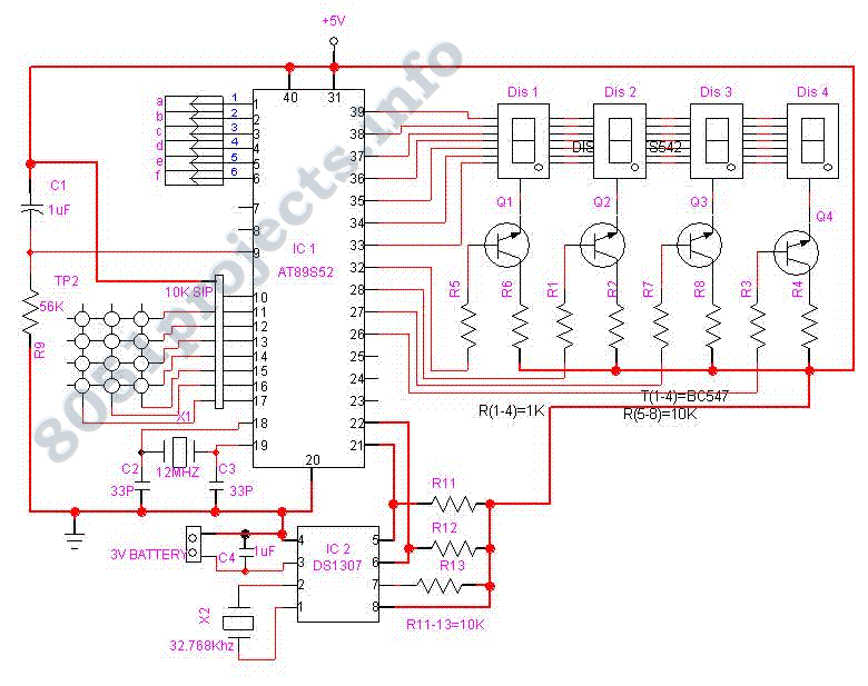
The Power Saving Using Time Operated Electrical Appliance Controlling System is designed to automate the control of electrical devices based on a pre-defined schedule, significantly enhancing energy efficiency and convenience. The core component of this system is a microcontroller, which interfaces with a real-time clock (RTC) module to keep track of the current time and date.
The RTC module, such as the DS3231, provides precise timekeeping and is connected to the microcontroller via I2C communication. The microcontroller continuously reads the time from the RTC and compares it with user-defined switching times stored in its memory.
User interaction is facilitated through a keypad, allowing users to input desired switching times. The keypad is connected to the microcontroller, which interprets the input and updates the stored times accordingly. This feature enables dynamic scheduling, where users can modify the switching times without needing to reprogram the entire system.
The output control of the system is managed through relays that are activated by the microcontroller. Each relay corresponds to a specific electrical device, and when the current time matches the programmed time, the microcontroller sends a signal to activate the appropriate relay, thereby turning the device ON. Conversely, the relay can be deactivated after a specified duration or at a predetermined time, thus turning the device OFF.
The real-time clock's output is visually represented on four 7-segment displays, allowing users to easily monitor the current time at a glance. The display is controlled by the microcontroller, which sends the necessary signals to illuminate the appropriate segments based on the time data received from the RTC.
Overall, this circuit design not only automates the control of electrical appliances but also promotes energy conservation by ensuring that devices are only operational when needed. The combination of a real-time clock, user-friendly keypad interface, and relay control makes this system a practical solution for modern energy management in residential or commercial settings.Power Saving Using Time Operated Electrical Appliance Controlling System is a reliable circuit that takes over the task of switch on/off the electrical devices with respect to time. This project replaces the Manual Switching. It has an Inbuilt Real Time Clock which tracks over the Real Time. When this time equals to the programmed time, then the corresponding Relay for the device is switched ON. The switching time can be edited at any Time using the keypad. The Real Time Clock is displayed on four 7-segment display. 🔗 External reference
Related Circuits
AMIS-49200-XTP is a subpackage of AMIS-492X0. For further information, please refer to the description of AMIS-492X0. The datasheet for AMIS-49200-XTP can be downloaded from the link provided below. By ON Semiconductor. The AMIS-49200-XTP is a specialized integrated circuit designed for...
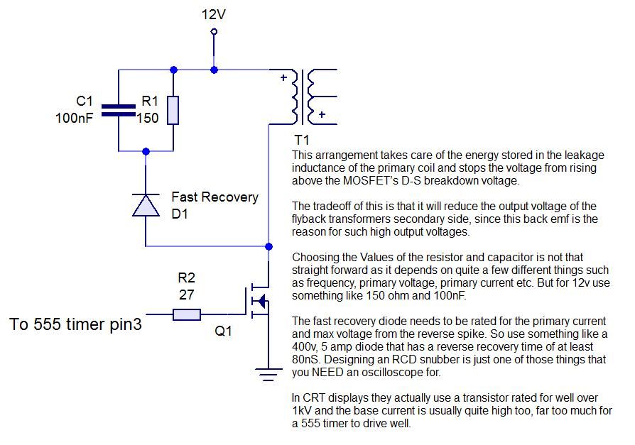
This instructable demonstrates the process of creating an audio-modulated plasma speaker using a flyback transformer salvaged from an old CRT display. The audio-modulated plasma speaker operates by utilizing a high-voltage output from a flyback transformer to create a plasma arc...
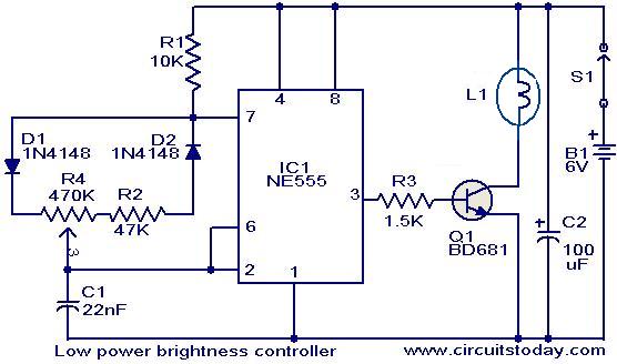
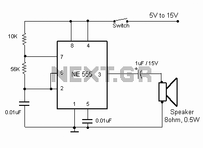
The circuit presented here is designed to control the brightness of low-power incandescent lamps. It utilizes the NE555 integrated circuit, configured as an astable multivibrator with a variable duty cycle. The output from the IC is connected to the...
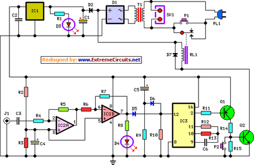
This circuit deactivates an amplifier or any connected device when a low-level audio signal is absent at its input for at least 15 minutes. Activating switch P1 powers the device, enabling operation of any appliance connected to SK1. The...
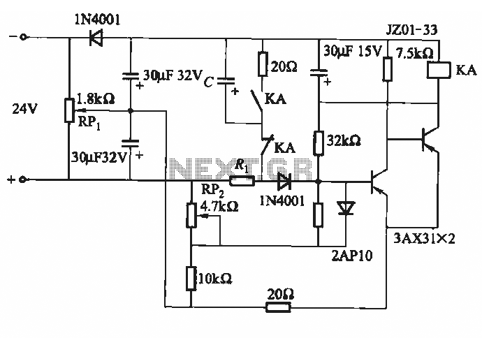
This circuit consists of five transistor time relay circuits designed for time relay exchange. It utilizes two different power supplies, maintaining the same circuit configuration. The delay time can be adjusted by modifying a potentiometer. The parameters for the...
This simple electronic buzzer circuit is based on a timer that operates to generate sound frequencies. The NE555 integrated circuit is utilized as an astable multivibrator, functioning at approximately 1 kHz to produce sound when powered on. The frequency...