
Remote Control Tester
The remote control tester circuit typically consists of a photodiode or phototransistor, which is sensitive to infrared light emitted by the remote control. When the remote is activated, it emits infrared signals that the photodiode detects. The circuit may also include an LED indicator that lights up when infrared signals are detected, providing a visual confirmation of the remote's functionality.
A basic schematic of this circuit would include the following components:
- **Photodiode/Phototransistor**: This component is the heart of the circuit. It converts the incoming infrared light into an electrical signal. The choice between a photodiode and a phototransistor depends on the desired sensitivity and response time.
- **Resistor**: A resistor is connected in series with the photodiode to limit the current flowing through it, ensuring that it operates within safe limits.
- **LED**: The LED serves as an indicator. When the photodiode detects infrared light, it generates a voltage that is sufficient to forward-bias the LED, causing it to illuminate.
- **Power Supply**: The circuit requires a power source, which can be a simple battery or a DC power supply, depending on the design requirements.
The layout of the circuit should ensure that the photodiode is positioned to receive the infrared signals directly from the remote control, while the LED is placed in a visible location for easy observation. The simplicity of this circuit makes it an excellent project for beginners in electronics, allowing them to understand the principles of infrared communication and basic circuit design.
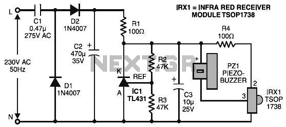
In summary, this remote control tester circuit is an effective tool for quickly checking the operational status of infrared remote controls, making it a valuable addition to any electronics toolkit.Here is the remote control tester circuit. This circuit is really a simple and easy tester for verifying the basic operations of an infrared remote control unit. It is low-cost and very easy to construct. The tester is designed around infra. 🔗 External reference
Related Circuits
In certain industries, a computer-controlled 4-20 mA current loop is utilized to manage various equipment. This current loop is employed to transmit a signal over a distance. The 4-20 mA current loop is a standard method for transmitting analog signals...
The personal radar system utilizes the PIC microcontroller PIC18F452 as a hobby project. The attached circuit diagram of the radar may appear simple; however, careful analysis of the PIC18F452 radar circuit is necessary to prevent damage. This personal radar...
The MC33411 900 MHz Analog Cordless Phone Baseband system is designed to meet the specifications of a 900 MHz Analog cordless telephone system. It includes three Phase-Locked Loops (PLLs). Two of these PLLs are intended for use with external...
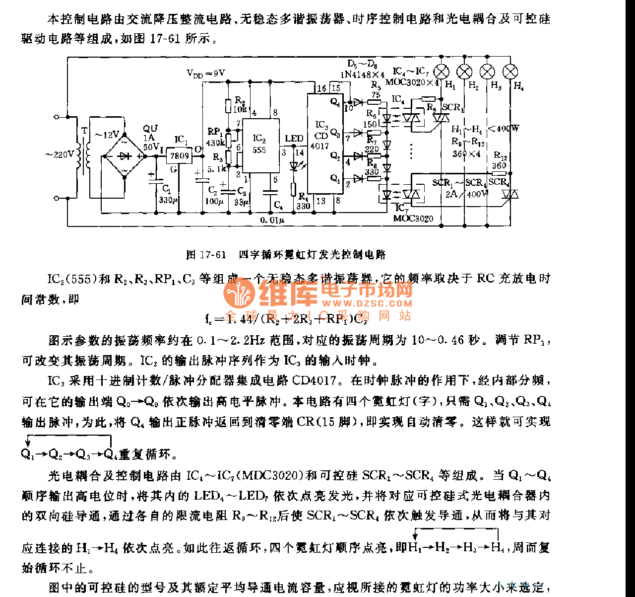
This control circuit consists of an AC step-down rectifier circuit, an astable multivibrator, a timing control circuit, an optocoupler circuit, and an SCR driving circuit, as illustrated in Figure 17-61. The astable multivibrator is formed using IC2 (555), resistors...
This simple DC motor control or PWM circuit using a 555 IC can be utilized to regulate the speed of a DC motor. The circuit is straightforward and can be assembled quickly if all components are readily available. The described...
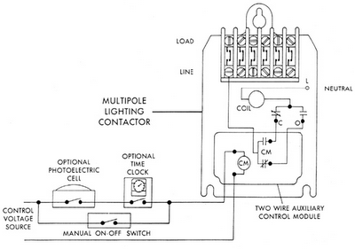
Sensors for lighting controls include photoelectric sensors and presence detectors. Photoelectric sensors typically switch lighting on at dusk and off at dawn, with adjustable settings for sensitivity to light levels. They feature built-in time delays to prevent unwanted switching...
Warning: include(partials/cookie-banner.php): Failed to open stream: Permission denied in /var/www/html/nextgr/view-circuit.php on line 713
Warning: include(): Failed opening 'partials/cookie-banner.php' for inclusion (include_path='.:/usr/share/php') in /var/www/html/nextgr/view-circuit.php on line 713