
Remote-Control Tester Circuit
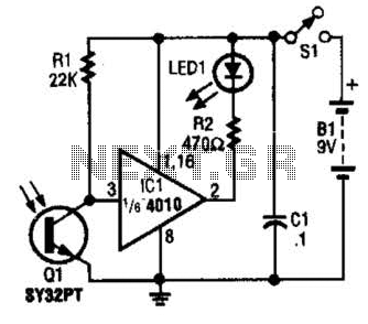
The IR Tester circuit operates by detecting infrared signals emitted by remote control devices when a button is pressed. The core component, Q1, is a phototransistor that responds to these IR signals by changing its conductivity. When IR light from the remote control reaches Q1, it generates a current flow through the phototransistor, which can be used to trigger an output indication, such as an LED or a buzzer.
In a typical configuration, the circuit may include a power supply, a resistor for current limiting, and an output device. The power supply can be a battery or any suitable DC source, providing the necessary voltage for the circuit operation. The resistor is connected in series with Q1 to ensure that the current flowing through the phototransistor remains within safe limits, preventing damage and ensuring reliable operation.
The output device, often an LED, is connected to indicate the presence of IR signals. When the remote control button is pressed, and the phototransistor is activated by the IR light, the LED will illuminate, providing a visual confirmation that the remote control is functioning correctly. In some designs, a buzzer may be used instead of an LED for audible feedback.
The circuit can be further enhanced by adding a variable resistor (potentiometer) to adjust the sensitivity of the phototransistor, allowing it to detect IR signals from various remote controls with different output power levels. Additionally, the circuit may include a small capacitor to filter any noise from the detected signal, ensuring that only valid IR signals trigger the output indication.
This simple yet effective design is useful for troubleshooting remote control devices and ensuring that they are operational, making it an essential tool for electronics enthusiasts and technicians. The IR Tester circuit lets you know if the button you press on a remote control is working. Ql is a photo transistor that is activated by IR energy. 🔗 External reference
Related Circuits
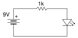
Beginner's Tutorial 1: Building a Circuit on Breadboard - how to build a simple and easy circuit on a breadboard for beginners in electronics. Learn to use an LED and a resistor. This tutorial serves as an introductory guide for...

The noise limiter circuit features a preamplifier clipper and a switchable audio bandpass filter. Audio levels ranging from 5 to 50 mV are amplified in a preamplifier to several volts peak-to-peak, which are then sent to a clipper and...

This design circuit is for audio graphic equalizers, which are commonly found in commercial products, yet circuits for them are rarely published. The circuit features a simple design that requires an operational amplifier (op-amp) to amplify the input signal....
A microprocessor cannot drive a motor directly since it cannot supply enough current. Instead, an interface circuit is required so that the motor power is supplied from another source, with only control signals derived from the microprocessor. This interface...
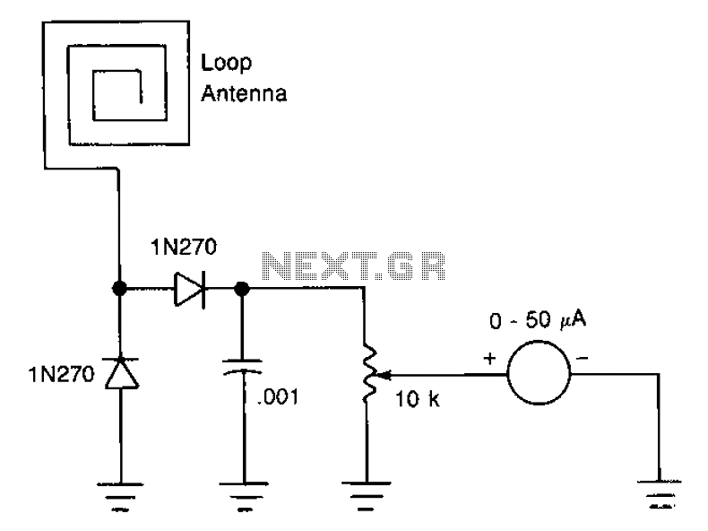
The antenna consists of approximately 20 cm of insulation made from strands, which are glued together inside a small plastic box. An RF current is processed through two diode rectifiers, and a 10k potentiometer is connected to the pin...

The circuit features simple smart temperature sensors utilizing an I2C bus interface, designed as a thermostat controller circuit. It employs the LM75 temperature sensor connected to a 2N3904 transistor, which drives a relay coil. The relay operates based on...