
Remote Control Using Radio Telephone
The remote control circuit employs radio frequency (RF) technology to facilitate wireless communication between a transmitter and a receiver. The transmitter typically consists of a microphone, RF oscillator, and a modulator. The microphone captures audio signals, which are then converted into electrical signals. The RF oscillator generates a carrier wave, and the modulator combines the audio signal with the carrier wave for transmission.
On the receiving end, the circuit includes an RF receiver, which demodulates the incoming signals to extract the original audio information. This signal can then be used to control various appliances, such as lights or motors, by interfacing with a relay or a microcontroller. The relay acts as a switch, enabling or disabling the power to the connected appliance based on the received command.
The range of the remote control system can be influenced by factors such as the power output of the transmitter, the sensitivity of the receiver, and environmental conditions. Antennas play a critical role in enhancing the transmission and reception quality, with suitable designs ensuring optimal performance.
In summary, this remote control circuit diagram represents a practical application of radio frequency technology, allowing users to operate devices wirelessly from considerable distances, thereby providing convenience and flexibility in various settings.This circuit shows about Remote Control Using Radio Telephone Circuit Diagram. Features: used to switch appliances from any distance, overcoming .. 🔗 External reference
Related Circuits
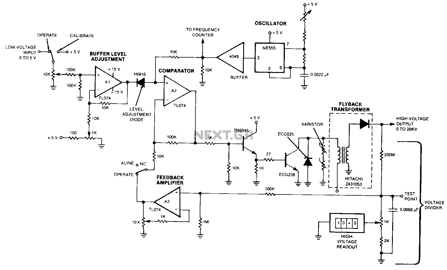
The output voltage varies approximately linearly up to 20 kV as the input voltage is adjusted from 0 to 5 V. A 5-0 potentiometer is used to tune the oscillator, optimizing the output voltage at the frequency of maximum...
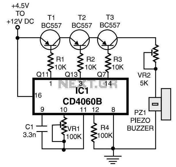
This page features a circuit that has twenty open collector outputs that turn on one at a time in a continuous sequential manner. The circuit utilizes the 74LSxx family of TTL integrated logic devices. The circuits are designed to...
Touch controls are not only utilized for switching devices on or off but can also manage various functions. A notable example is the TV remote control. When it is crucial to maintain activated functions for an extended period, employing...
Join the forum discussion on this post. This is a simple home telephone ringtone generator circuit built using only a few electronic components. It generates a simulated telephone ringtone and requires only a DC supply. The home telephone ringtone generator...
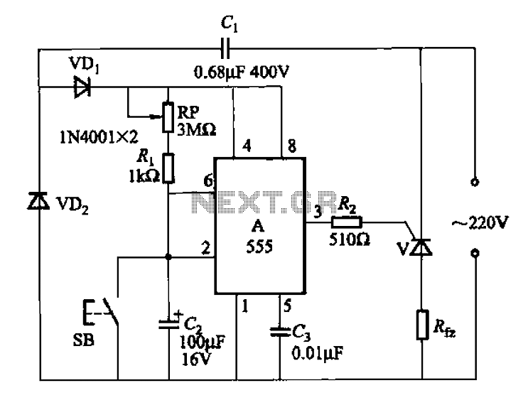
The 555 integrated circuit (IC) is utilized in a delay circuit configuration. It transitions from a high to a low output state when a button (SB) is pressed. The output remains high for a specified delay period before transitioning...
A pulse motor, commonly known as a stepper motor, is defined as a motor that changes its excitation state according to input pulse signals, allowing it to move forward at a specific angle or distance. If the excitation state...