
Remote Controlled Alarm circuit

The remote-controlled alarm circuit is designed to enhance the safety and comfort of elderly patients or individuals with limited mobility. The use of the TSOP1736 sensor allows for reliable operation with commonly available infrared remote controls, ensuring that the system is accessible and user-friendly. The integration of noise suppression components, such as the bandpass filter and automatic gain control, ensures that the alarm operates effectively in various environments, reducing the likelihood of false alarms caused by ambient infrared interference.
The active piezo buzzer serves as the primary alert mechanism, providing an audible signal that can be easily heard by caregivers or family members. The inclusion of the visual alert in the form of a red LED adds an additional layer of notification, making it easier for individuals to identify when the alarm has been activated, especially in noisy or busy environments.
When constructing the circuit, careful attention should be paid to the placement of the infrared sensor, as it must have a clear line of sight to the remote control for optimal performance. The transparent enclosure not only protects the components but also allows for easy visibility of the LED indicator. The use of a 9V alkaline battery ensures that the system remains portable and can be easily relocated as needed.
Overall, this remote-controlled alarm circuit represents a practical solution for enhancing communication and safety for patients and elderly individuals, facilitating prompt assistance when needed.A very interesting remote controlled alarm circuit using TSOP1736. Routing of an electric cable to attach a calling bell switch near the bed of an old age/patient is not a good idea. Here is an ultra simple battery operated remote controlled alarm to help old age members/patients in bed, especially at home/hospital.
Any tv/video infrared remote co ntrol handset (36Khz) can be used to arm the alarm! At the heart of the circuit is the popular integrated infrared sensor TSOP1736. The TSOP1736 is a miniaturized receiver for infrared remote control systems. PIN diode and preamplifier are assembled on lead frame, the epoxy package is designed as an infrared filter. Further, a bandpassfilter, an integrator stage and an automatic gain control are used to suppress unwanted noise disturbances.
When a person needs immediate attention of someone, he should firmly press and hold any button in the keyapad of the remote control handset and aim the handset towards the sensor (IRRX) of the alarm circuit. Instantly, the active piezo-buzzer stars beeping in tune with the modulated infrared signals emitted by the handset.
Sametime, a good visual alert is provided by the red colored 10mm LED(D2). After construction, enclose the whole remote controlled siren unit in a transparent cabinet with the Infrared sensor at the front side of the box. Now power the circuit through a suitable 9V compact alkaline battery. Insertion of an ordinary on/off toggle switch in the positive rail is a good idea. After successful testing, mount the unit in a proper point at the wall of the room/hall, as per the requirement.
Finally, the lab prototype is connected to a multidirectional 5V dc buzzer. However, you can use an ordinary 5V dc buzzer or any kind of 5V active piezo-sounder. 🔗 External reference
Related Circuits

Infrared (IR) Motion Detector Circuit featuring a motion detector alarm and an infrared sensor. The circuit diagram and its operation are provided in detail. The infrared (IR) motion detector circuit is designed to detect motion within a specified range and...
The tuner is programmable via I²C-Bus and provides a FBAS signal at its output. There is also the homepage of Georg Acher containing information about this tuner. A control circuit has been developed for this tuner using the AT89C2051...

A charged capacitor C3 and a momentary pushbutton switch S2 are utilized to temporarily activate relay RE2. The battery being charged powers the relay to maintain its closed state. Additionally, S2 can energize the relay even if the battery...

LCD modules have become a popular means of displaying system messages and status in embedded applications. This application note demonstrates how to interface an SST FlashFlex microcontroller to a typical character LCD module. The SST FlashFlex is an industry-standard,...

The hobby circuit described utilizes a unique approach to generate approximately 12,000 volts with a current of about 5 µA. It employs two silicon-controlled rectifiers (SCRs) that form dual pulse generator circuits. These SCRs discharge a 0.047 µF capacitor...
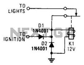
A relay and two diodes are all that is needed; the relay performs the job of a buzzer, so no annunciator is required. When the lights are left on while the ignition is off, the normally closed relay contacts...