
Circuit Project: 12KV High Voltage Generator

The circuit operates on the principle of pulse discharge through SCRs, which are semiconductor devices that can control current flow. When triggered, the SCRs allow the discharge of the capacitor through the xenon lamp trigger coil, creating high-voltage pulses. The frequency of 120 Hz indicates that the SCRs are triggered at regular intervals, allowing for consistent pulse generation.
The output from the trigger coil is stepped up in voltage, and the two 6 kV damper diodes rectify the alternating high-voltage pulses into a direct current. The voltage doubler circuit effectively doubles the voltage output, charging the two high-voltage disc capacitors to approximately 12 kV. This configuration is critical for applications requiring high voltage, such as igniting gas discharge lamps or in certain experimental setups.
Safety measures are paramount when working with high-voltage circuits. The design must ensure sufficient spacing between components to prevent arcing and accidental discharge. Proper insulation and the use of components rated for high voltage are also essential to prevent failures and ensure reliable operation. Overall, this circuit exemplifies a creative approach to generating high voltages in a compact and efficient manner, though it requires careful handling and consideration of safety protocols.The hobby circuit below uses an unusual method to generate about 12, 000 volts with about 5uA of current. Two SCRs form two pulse generator circuits. The two SCRs discharge a 0. 047uF a 400v capacitor through a xenon lamp trigger coil at 120 times a second. The high voltage pulses produced at the secondary of the trigger coil are rectified using two 6KV damper diodes. The voltage doubler circuit at the secondary of the trigger coil charges up two high voltage disc capacitors up to about 12KV. Although this circuit can`t produce a lot of current be very careful with it. A 12KV spark can jump about 0. 75 of an inch so the electronic circuit needs to be carefully wired with lots of space between components.
🔗 External reference
Related Circuits
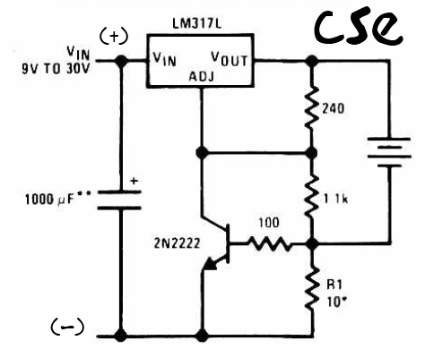
This is a straightforward charger designed for 9V to 30V batteries, primarily operated by the IC LM317L and a 2N222 transistor. It utilizes direct input DC voltage, and a recommended capacitor of 1000µF is included for filtering the output...
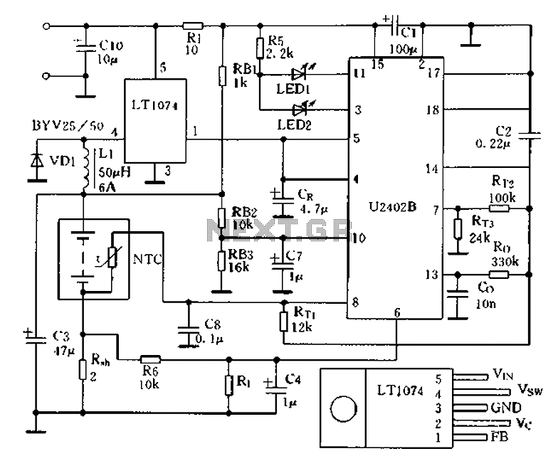
Charging circuit from the DC power supply switching power supply control The charging circuit described is designed to operate with a DC power supply, utilizing a switching power supply control mechanism. This type of circuit is commonly employed in applications...

This circuit operates effectively across a broad frequency spectrum. XTAL 1 serves as a fundamental-frequency crystal. Tl and CI are adjusted to match the input frequency. This circuit can be utilized as a straightforward shortwave converter for AM radios,...
The circuit illustrates a two-stage voltage amplifier that drives a recording level meter. An AC signal input is amplified and rectified, with the resulting DC voltage displayed on the meter. This circuit is compatible with tape recorders or audio...
A voltage supply ranging from 6 V to 15 V is required when using a single LED per module. An increase in the number of LEDs necessitates a corresponding increase in the voltage supply, with additional LEDs connected in...
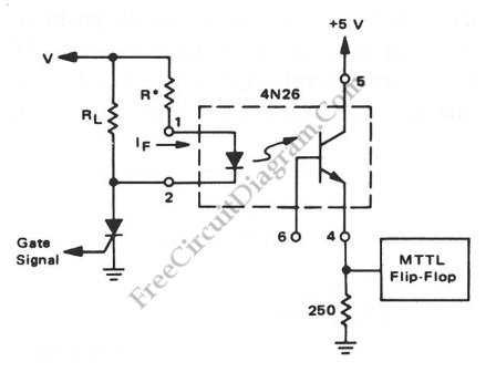
Interfacing high power loads can be accomplished in various ways, including the use of voltage divider resistors, transformers, or optocouplers. The circuit illustrated below employs the optocoupler method. This optocoupler facilitates logic level translation with flexible input, accommodating a...