
Telephone repeater circuits
The telephone repeater circuit functions by receiving the incoming audio signal from a telephone line and amplifying it to enhance the clarity and volume of the sound. The primary components of this circuit typically include a microphone for capturing the audio signal, an operational amplifier (op-amp) for amplification, and a speaker for outputting the enhanced sound.
In practical implementations, the circuit may utilize a power supply to ensure sufficient voltage levels for the op-amp, which can be configured to provide a desired gain. The circuit design may also include filters to eliminate unwanted noise and ensure that only the relevant frequency range of the audio signal is amplified.
To improve the performance of the repeater, feedback mechanisms can be incorporated to stabilize the amplification process and prevent distortion. Additionally, the circuit can be designed with user controls, such as volume knobs, to allow for adjustments based on individual preferences.
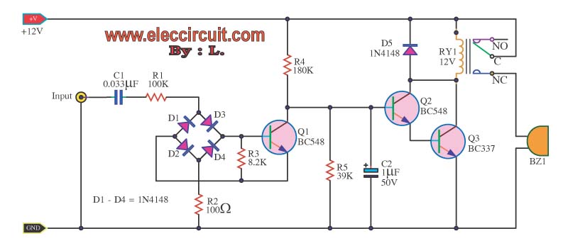
The telephone repeater is particularly useful in environments where the original sound is too faint, ensuring that the communication remains clear and effective. This circuit can be applied in various settings, including home telephony systems, public announcement systems, and any scenario where audio signals require amplification for better audibility.The telephone repeater or The call signal peripheral circuit to the loud than the original. It`s a circuit that we design follow the request. One of my friends 🔗 External reference
Related Circuits
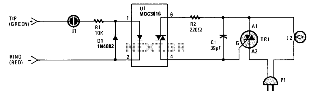
A small neon lamp is activated by the telephone's ringing voltage, allowing a sufficient current to flow to the LED in optocoupler U1. This activation subsequently triggers a 6-A Triac that controls a 117-Vac lamp or bell. Capacitor C1...
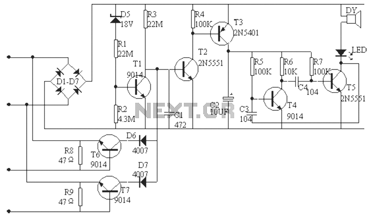
The phone alarm device is designed to monitor and prevent unauthorized use of a telephone line. When interference signals are detected on the line due to theft attempts, the alarm activates, preventing the thief from making calls while alerting...

The circuit employs a field-effect transistor (FET) at the input of a Schmitt trigger, allowing the use of a low-value capacitor. The trigger, controlled by Q1 and O2, exhibits a hysteresis of approximately 3V, regulated by a 3V zener...
This circuit describes a simple 6-bit random number pseudo-generator used to study binary counters and, in particular, shift registers. Some basic background information about binary counters and shift registers is provided. In reality, there are dozens of different shift...
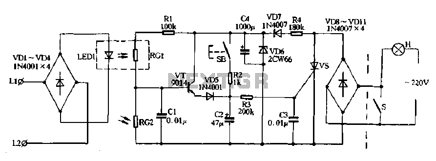
Diodes VD8 to VDI1 function as part of the main circuit isolation, with SCR serving as a composition control switch. The buck regulator circuit is composed of a stable orbital tube VD6 and a simple resistor-capacitor combination (C4). The...
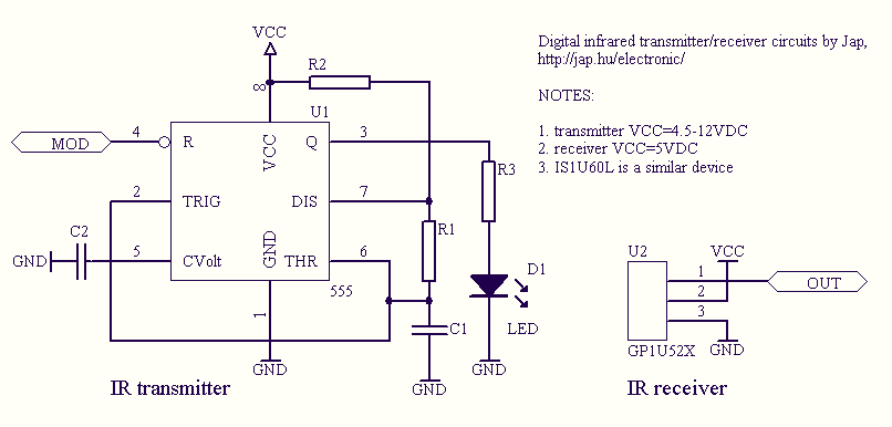
Infrared remote controls are using a 32-56 kHz modulated square wave for communication. These circuits are used to transmit a 1-4 kHz digital signal (OOK modulation) through infra light (this is the maximum attainable speed, 1000-4000 bits per sec)....