
Remote Controlled Locomotive
ards for the safe riding of staff, and a radio-controlled remote system which allows the operator to leave the cab to couple wagons and still be able to drive the locomotive from a distance. The Meccano model is built to a scale of 1:17 and runs on 2. 5" gauge track. Two Richards motors with six speed gearboxes provide the motive power (one per bogie, with only one axle driven on each bogie).
The gearing used provides a scale top speed of about 20km/h, while developing enough torque to move six bogie container wagons through four-metre radius reverse curves in a shunting yard. I wanted to add electronics to be able to drive the locomotive in prototypical fashion, `by remote`. The model had to be self-powered, as the pointwork in the shunting yard made any idea of insulated rails for power feeding a bit of a nightmare.
The solution came in the form of an infra-red (IR) remote control system from Oatley Electronics. This kit was originally designed for the remote control operation of stereo equipment, and is comprised of a nice handheld remote transmitter unit and an 8-channel IR Receiver Module. The IR Receiver Module is interfaced to a Pulse Width Modulation (PWM) drive unit, a kit from Dick Smith Electronics designed originally as a light dimmer or motor speed controller for use in cars.
With a switching capacity of 10A it easily runs the two Richards motors wired in parallel. Power is supplied by two lead-acid gel cells of 12V, 1. 3Ah, wired in parallel, which store enough energy to give several hours of shunting at an exhibition. The prototype locomotives have two strobe units on the sloping roof sides of the cab, which alternately do a double flash.
I simulated this with a little digital circuit which drives high-intensity yellow LEDs. This circuit is also wired in parallel with the motors, so that the LEDs only flash when the locomotive is moving (as the real ones do). The IR Receiver Module originally had its IR sensor mounted on the circuit board; I removed it to a separate piece of stripboard and connected it to the module via a two-core coaxial cable.
The IR commands are decoded by the module and are used to drive eight independent relays, five of which are used on this model. In the figure the contacts of these relays are labeled K1 to K5, and all are shown in their `rest` state (i.
e. controller button not pressed). To get the model to move, firstly `Forward` or `Reverse` direction must be selected by pushing the appropriate button on the remote control. The corresponding power relay RL1 or RL2 operates and self-latches on one of its contacts. The other contact of the power relay sets up the traction motor circuit from the positive supply line, through the motors, to the negative supply line via a MOSFET power transistor in the PWM drive module.
A `Stop` button is used to release the latched power relay (via the K1 receiver relay), which is necessary when changing direction, and also provides an instant `emergency stop` function. Capacitors C1 and C2 wired across the motor brushes are to suppress the electrical noise created by the motors, which could otherwise interfere with the operation of the electronics.
Diodes D1 and D2 are fitted to the relays to prevent voltage spikes from being generated when the relays release. These spikes could potentially be large enough to damage the electronics if diodes were not fitted. We now need to get the traction motor current going. The PWM Module does this by switching the MOSFET transistor on and off rapidly, at a fixed frequency but variable duty cycle.
This technical t 🔗 External reference
Related Circuits
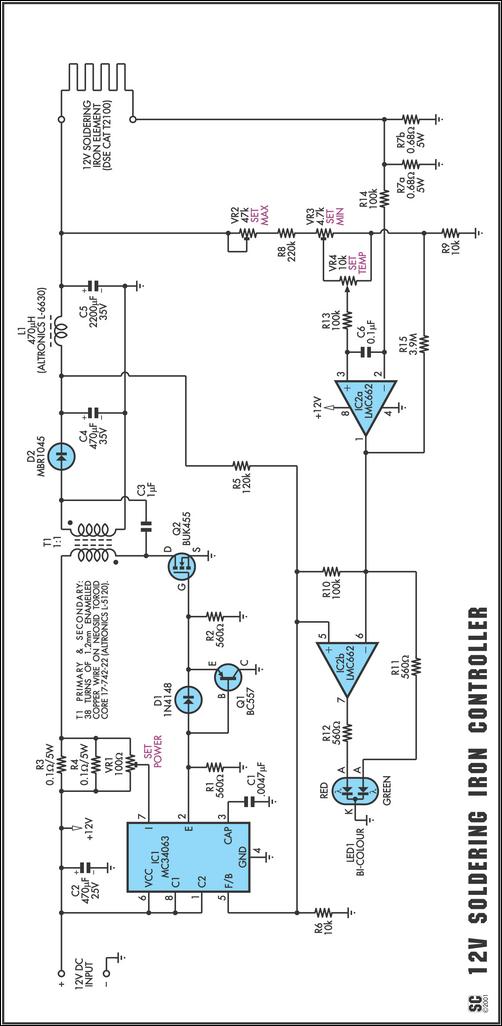
One reason commercial soldering stations are expensive is that they generally require soldering irons with built-in temperature sensors, such as thermocouples. This circuit eliminates the need for a special sensor by sensing the temperature of a soldering iron heating...

A mobile-controlled robot is a mobile device that offers extensive wireless control capabilities to the robot, as long as the cell phone remains within signal range. The mobile-controlled robot operates through a wireless communication interface, typically utilizing Bluetooth or Wi-Fi...

A replacement remote control system for an electric garage door was constructed after the original remote failed multiple times. Although the old remote could have been repaired, it was 35 years old and not particularly enjoyable to use. The...
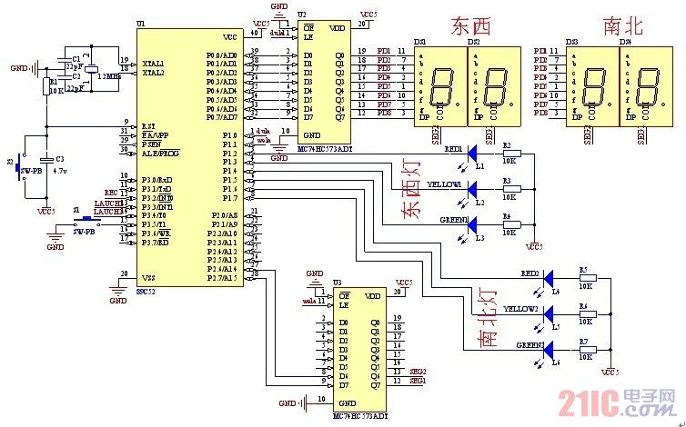
A steady, flexible, and convenient traffic light control system is essential for effective traffic management. In practice, many traffic lights operate on a time interval basis. This design allows for the adjustment of switching times for traffic lights during...
The circuit consists of two main components: (1) a power supply circuit featuring a transformer (T) that steps down AC 220V to 33V, followed by a full-wave rectifier, a filter, and a three-terminal regulator that outputs +24V. This circuit...
Infrared remote controls are using a 32-56 kHz modulated square wave for communication. These circuits are used to transmit a 1-4 kHz digital signal (OOK modulation) through infra light (this is the maximum attainable speed, 1000-4000 bits per sec)....