
Remote Doorbell Controller
.jpg)
The proposed circuit design for the remote doorbell enhancement integrates several key components to ensure reliable operation. The 555 timer is configured in a monostable mode, allowing it to output a single pulse when triggered. This pulse duration can be adjusted by changing the resistor and capacitor values associated with the timer. The 78L12 voltage regulator stabilizes the input voltage to the 555 timer, ensuring consistent performance regardless of variations in the input voltage from the doorbell system.
The 2N3904 transistor acts as a switch, allowing the 555 timer's output to control the relay. The relay serves as an interface between the low-voltage circuit and the transmitter module, enabling safe operation without direct exposure to the higher voltage of the doorbell system. The use of a reed relay minimizes power consumption and enhances the overall efficiency of the circuit.
When the doorbell button is pressed, the circuit is activated, causing the 555 timer to generate a pulse that energizes the relay. This pulse duration can be fine-tuned by adjusting the resistor R5, allowing for flexibility in how long the transmitter is activated. The transmitter, once triggered, sends a signal to the receiving unit, which alerts the user through audible sounds.
In summary, this project provides a practical solution for enhancing doorbell functionality, particularly for those with hearing challenges in specific areas of the home. The integration of a remote transmitter and receiver, combined with the efficient use of a 555 timer and relay, results in a user-friendly and effective doorbell system.I usually can`t hear the doorbell when I`m in the basement. This project describes how to add an inexpensive remote doorbell to your existing household doorbell. My doorbell runs off of a 24VAC transformer that is live all the time. Someone presses the button and the bell sounds. To implement this project, it is necessary to tap 3 conductors from the system: 24VAC, common, and doorbell. The doorbell signal is the one that is live only when the button is pressed. You also need a remote doorbell kit. I found a very inexpensive one on eBay, consisting of a small transmitter unit with a pushbutton, and a receiving unit with a speaker. The transmitter is very simple. It takes a tiny 12V battery (supplied), and you`re supposed to stick it next to your door with double-sided tape.
The receiver takes 2 AAA batteries. As a bonus it sounds numerous tunes, including christmas carol jingles, so you`re bound to find one that you like. I don`t like products like this that use batteries that require replacement, and you`ll find in my project none are needed.
I designed this circuit for the sending unit: A 555 timer, powered on all the time, is used as a timed one-shot. The timer is triggered by the signal from the doorbell button, conditioned by a 78L12 regulator and a 2N3904 transistor.
The remote transmitter is triggered by the output of the 555, using a small reed relay. The relay I used was a 5V unit, so I placed a 560 ohm resistor in series to the 555 timer. 12 volts from the relay switch is applied to the transmitter module battery terminals. Oh yes, you must short the pushbutton in the transmitter module for this to work! Remove the transmitter from its case, short out the pushbutton and connect two wires to the battery terminals. When the doorbell button is pressed, the 555 is triggered and drives the relay for 1 to 2 seconds, depending on R5.
The transmitter then sends its signal. SW1 is actually a SPDT pushbutton. It is handy to test the remote doorbell without sounding the house doorbell. If you can`t find a SPDT pushbutton, you can simply omit it or substitute a jumper or toggle switch. 🔗 External reference
Related Circuits
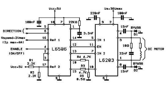
The L620x is a monolithic full bridge switching motor driver implemented using the new Multipower-BCD technology. This technology enables the integration of multiple isolated DMOS power transistors along with mixed CMOS/bipolar control circuits. The L620x series includes various versions:...
As summer approaches, many individuals focus on staying cool during hot days. For some, this means turning on the air conditioner and enjoying a cold beverage. However, it is essential to consider how to maintain the temperature of radio...
A PIR sensor is triggered when using a timer to wait for 2 seconds after the sensor is activated. Without the timer, the sensor operates as intended. The PIR sensor is connected to an ATMega328p microcontroller, which has three...

The PS10 saves board space, improves accuracy, eliminates optocouplers or level shifts, and reduces overall component count by combining four programmable timers, input under-voltage (UV) and over-voltage (OV) supervisors, a programmable power-on reset (POR), and four 90V open drain...

This design outlines a door alarm circuit that utilizes an electronic system. It features a synthesized sound chip from Holtek, specifically the HT-2811, which reproduces the sound of a "ding-dong" chiming doorbell. The circuit also incorporates a CMOS 4026...
Faulty readings from the DS18B20 temperature sensors used in tank thermometers were likely caused by the waterproofing method involving heat shrink and silicone. This situation provided an opportunity to enhance the code for better tolerance against erroneous readings. The...