
Remote control ultrasonic switch
The described circuit operates on the principle of ultrasonic sound transmission and reception, utilizing a dual-component system comprising a transmitter and a receiver. The transmitter employs a 555 timer configured in astable mode to generate ultrasonic waves in the frequency range of 40 to 50 kHz, beyond the audible spectrum for humans. The choice of frequency can be adjusted using the variable resistor VR1, allowing for fine-tuning to optimize performance based on environmental conditions.
The ultrasonic transducer in the transmitter efficiently converts the electrical oscillations generated by the 555 timer into ultrasonic sound waves. This sound is then directed toward the receiver, which includes an ultrasonic receiver transducer designed to detect these high-frequency signals. Upon receiving the ultrasonic waves, the transducer converts them back into electrical signals, which are subsequently amplified by a two-stage transistor amplifier (T3 and T4).
After amplification, the signals undergo rectification and filtering to produce a stable DC voltage. This DC voltage is fed into the inverting input of operational amplifier IC2, while the non-inverting input is connected to a variable DC voltage through preset resistor VR2. This configuration allows the user to set a threshold level, ensuring that only signals above a certain strength will trigger the relay.
The output of the op-amp is inverted and used to control a transistor driver stage, consisting of transistors T5 and T6. When the op-amp output goes low, transistor T5 is activated, which in turn biases T6, allowing current to flow through the relay coil, thereby actuating the relay. The relay can be utilized to switch on or off various electrical devices, making this circuit versatile for remote control applications.
To enhance functionality, a DPDT relay can be employed for latching capabilities, enabling the circuit to toggle between on and off states. Additionally, a flip-flop could be integrated to maintain the state of the relay until explicitly changed. For applications requiring a timed activation, a monostable 555 timer can be introduced at the output of IC2 to control the duration of the relay activation.
It is important to note the directional nature of ultrasonic waves, necessitating precise alignment of the transmitter and receiver for reliable operation. Furthermore, the potential for false triggering exists due to the presence of natural ultrasonic sources, which may inadvertently activate the circuit, especially when utilizing a flip-flop configuration. Proper design considerations and testing should be undertaken to mitigate these issues.C ircuit of a new type of remote control switch is described here. This circuit functions with inaudible (ultrasonic) sound. Sound of frequency up to 20 kHz is audible to human beings. The sound of frequency above 20 kHz is called ultrasonic sound. The circuit described generates (transmits) ultrasonic sound of frequency between 40 and 50 kHz. As with any other remote control system this cirucit too comprises a mini transmitter and a receiver circuit. Transmitter generates ultrasonic sound and the receiver senses ultrasonic sound from the transmitter and switches on a relay.
The ultrasonic transmitter uses a 555 based astable multivibrator. It oscillates at a frequency of 40-50 kHz. An ultrasonic transmitter transducer is used here to transmit ultrasonic sound very effectively. The transmitter is powered from a 9-volt PP3 single cell. The ultrasonic receiver circuit uses an ultrasonic receiver transducer to sense ultrasonic signals. It also uses a two-stage amplifier, a rectifier stage, and an operational amplifier in inverting mode. Output of op-amp is connected to a relay through a complimentary relay driver stage. A 9-volt battery eliminator can be used for receiver circuit, if required. When switch S1 of transmitter is pressed, it generates ultrasonic sound. The sound is received by ultrasonic receiver transducer. It converts it to electrical variations of the same frequency. These signals are amplified by transistors T3 and T4. The amplified signals are then rectified and filtered. The filtered DC voltage is given to inverting pin of op-amp IC2. The non- inverting pin of IC2 is connected to a variable DC voltage via preset VR2 which determines the threshold value of ultrasonic signal received by receiver for operation of relay RL1.
The inverted output of IC2 is used to bias transistor T5. When transistor T5 conducts, it supplies base bias to transistor T6. When transistor T6 conducts, it actuates the relay. The relay can be used to control any electrical or electronic equipment. Important hints: 1. Frequency of ultrasonic sound generated can be varied from 40 to 50 kHz range by adjusting VR1. Adjust it for maximum performance. 2. Ultrasonic sounds are highly directional. So when you are operating the switch the ultrasonic transmitter transducer of transmitter should be placed towards ultrasonic receiver transducer of receiver circuit for proper functioning. 3. Use a 9-volt PP3 battery for transmitter. The receiver can be powered from a battery eliminator and is always kept in switched on position. 4. For latch facility use a DPDT relay if you want to switch on and switch off the load. A flip-flop can be inserted between IC2 and relay. If you want only an ON-time delay use a 555 only at output of IC2. The relay will be energised for the required period determined by the timing components of 555 monostable multivibrator.
5. Ultrasonic waves are emitted by many natural sources. Therefore, sometimes, the circuit might get falsely triggered, espically when a flip-flop is used with the circuit, and there is no remedy for that. 🔗 External reference
Related Circuits
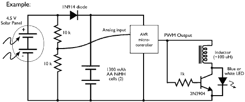
This example demonstrates the PWM (pulse-width modulation) output of a microcontroller controlling a Joule Thief style voltage booster to power a white LED. The circuit described utilizes a microcontroller to generate a PWM signal, which is an effective method for...
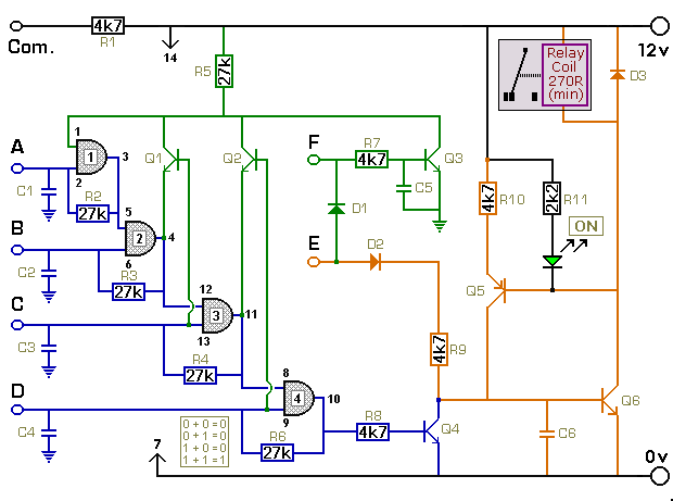
The key connected to "E" is used to energize the relay, while the four keys connected to A, B, C, and D are used to de-energize it. All other keys on the keypad are connected to "F". When "E"...
A simple circuit with which we have the possibility of opening and closing the RL1 contacts. It becomes active by touching a small metal surface. The status of RL1 is indicated by the LED D3. The supply voltage for...
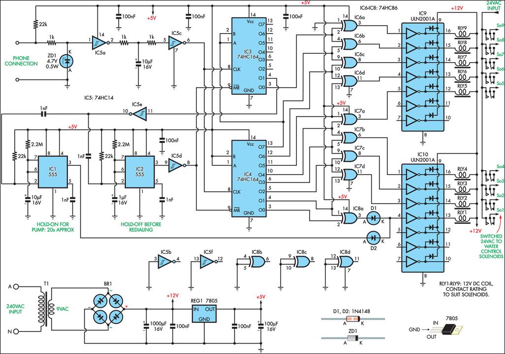
This remotely controlled watering system is cost-effective and easily expandable. It operates in conjunction with a conventional watering timer, enabling remote switching between nine zones. The prototype is designed for use with a bore system, where a deep-well pump...
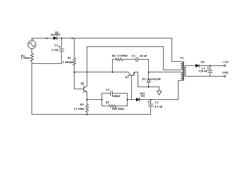
An old Nokia phone charger with a 5.6 V output was modified to provide 12 V by changing the Zener diode from a 9.1 V to a 16 V component. The circuit is mostly understood, but clarification is needed...
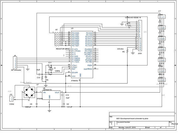
DTMF-based Robo Car design using the 8051 microcontroller project. This project demonstrates a method to control a domestic system using the DTMF tone generated by a telephone instrument when the user presses the keypad buttons of a mobile phone...