
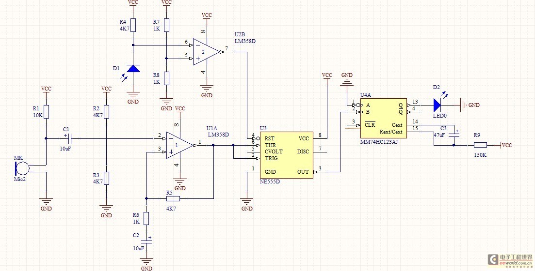
remote shift light
The proposed circuit modification involves utilizing an n-channel power MOSFET to replace traditional components, which streamlines the design while maintaining functionality. The MOSFET operates as a switch, controlling the power to the light bulb without the need for a relay, thus reducing size and complexity. The careful selection of the MOSFET is critical; it should be rated for the appropriate voltage and current levels to ensure safe operation without overheating. The inclusion of a resistor and capacitor in parallel at the transistor base is a prudent measure to mitigate transient voltages that could inadvertently trigger the bulb, thereby enhancing the longevity of the light source. The resistor between the gate and source of the MOSFET is essential for stability, preventing unintended activation due to floating inputs. The overall design should prioritize simplicity while ensuring that all necessary protective measures are in place to safeguard against potential electrical issues. This circuit can be effectively implemented in various applications, including automotive lighting systems, where reliability and efficiency are paramount. Proper documentation of the circuit design and thorough testing should be conducted to validate the functionality and safety of the modified circuit before deployment.If you replace the resistor/transistor with an n-ch power mosfet, and replace the relay/prot diode with a light bulb, you`ll have a simpler circuit that replicates the circuit you posted (assuming it drives a light bulb with one end connected to +12). If the Fet is chosen carefully, it won`t need a heatsink, and the whole circuit can be made on aconnecting block and have insulating tape
wrapped around it. THough having just said, the circuit you posted switches on when there is a voltage applied. You didn`t describe the existing LED circuit you wish to interface to. Can you tell us more about the LED circuit How is the LED driven The LED could be wired that way (low-side switched). You won`t know until you measure it, or look at the bike schematic. The more that can be found out about the existing circuit, the simpler the modification will be. If there isn`t this kind of information then the modification design becomes a little more complicated because it has to cater for all possibilities.
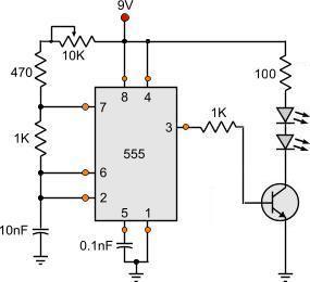
Some designers prefer to always cater for any possibilty (conservative) while other designers find out all they can, so as not to duplicate functionality (minimalist). I agree with marc to use the transistor to drive th ebulb direct, but allso you might want to put a capacitor and a resistor (both in parallel) from the transistor base to ground, this will reduce chance of it turning on with spikes and will provide a more gentle turn on/off of the bulb to increase bulb life.
Something like 3. 3k and 1uF should work. Roman Black - PICs and electronics. Author of BTc PIC-sound encoder, Shift1-LCD project, the TalkBotBrain talking PIC controller, LiniStepper open-source microstepping motor driver, the Black Regulator 2-transistor SMPS, and probably some other stuff; It`s the "done thing" to include a resistor (of a high-ish value, say 100K), between the gate and source, to prevent the Fet picking up signal when the input is unconnected floating. This would prevent the fet "half-turning on" (if the input was ever disconnected, the fet warming up and then melting the insulating tape wrapped around it and possibly burning a hole somewhere.
The resistor push into the same conn-block holes as the fet pins. Another `done thing` (more like a ritual) is the adding of a resistor in series with gate pin, the idea being that it "prevents oscillations at RF frequencies". I would say omit this gate series resistor completely (using the `KISS principle`), because you want to connect the FET`s 3 pins directly into a connecting block, not have to build a full `bells and whistles` circuit on a PCB!
When someone says something is "in the high side" this means for example as applied to the good old fashioned Horn or Hooter circuit, where one side of the hooter is connected to +12. The hooter is in the high side. The other side of the hooter is wired to the button, which completes the circuit to Ground. The button would be described as in the "Low Side". Take a different tack. what drives the LED Is it a Switch screwed into the Engine Block If so how many wires does Switch have Is one of these wires connect to ground Or maybe one connects to + 12V Or does the LED get driven from an ECU If so, could you measure the voltage of the LED, with respect to ground Do this by clipping your negative probe to ground and probe either side of the LED with the red probe.
🔗 External reference
Related Circuits
The optically-controlled circuit plays a crucial role in urban street lighting and corridor illumination. By utilizing this circuit, lighting lamps can be automatically turned on and off based on ambient light levels, thereby reducing the need for manual control,...
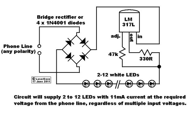
This circuit operates in a manner that allows the phone line to remain active while the LEDs are connected. When the phone is picked up, the light turns off, enabling normal phone usage. The phone line delivers 48V DC...
The wireless light switch circuit described here requires no physical contact for operating the appliance. You just need to move your hand between the infrared LED (IR LED1) and the phototransistor (T1). The infrared rays transmitted by IR LED1...
This device is a simple timer that keeps the headlights of a vehicle illuminated for approximately 1 minute and 30 seconds. This feature is particularly useful when accessing dark areas, eliminating the need to return to manually switch off...
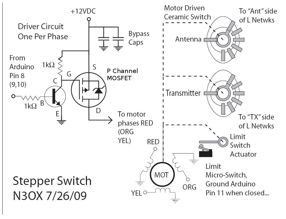
Information is needed regarding a circuit to manage the Remote Coax Ameritron RCS-10, as no diagram can be found on Google. The Ameritron RCS-10 is a remote coax switch designed for amateur radio applications, allowing users to control multiple antennas...
This is a simple circuit that anyone can create for enjoyment. The project originated when there was an attempt to control a TV using the serial port of a computer. It took only a few minutes to grasp the...