
LED (IR LED1) and the phototransistor (T1) and wireless light switch
 and the phototransistor (T1) and wireless light switch")
The wireless light switch circuit utilizes an infrared light-emitting diode (IR LED1) and a phototransistor (T1) to create a non-contact switch mechanism. The core of the circuit is based around the CA3140 operational amplifier, which provides the necessary gain and stability for the phototransistor's output signal. When a user moves their hand into the path of the infrared beam emitted from IR LED1, the phototransistor detects the change in light intensity, leading to a change in its conductive state.
This circuit operates at low power, making it energy-efficient for various applications, including lighting systems, automated doors, and other household appliances. The relay component acts as a switch that controls the power to the appliance. When the infrared beam is interrupted, the phototransistor triggers the relay, allowing current to flow to the connected device. The relay remains activated as long as the beam is interrupted. Once the hand is removed, the infrared light reaches the phototransistor again, causing it to turn off and subsequently deactivating the relay, which in turn powers down the appliance.
The design is compact and cost-effective, making it suitable for various applications where traditional mechanical switches may be impractical. The use of infrared technology enhances the reliability and longevity of the switch, as there are no moving parts that can wear out over time. Additionally, the low current consumption in milliamperes ensures that the circuit can operate efficiently without excessive energy use, contributing to its appeal in modern electronic applications.The wireless light switch circuit described here requires no physical contact for operating the appliance. You just need to move your hand between the infrared LED (IR LED1) and the phototransistor (T1). The infrared rays transmitted by IR LED1 is detected by the phototransistor to activate the hidden lock, flush system, hand dryer or else.
This w ireless light switch is very stable and sensitive compared to other AC appliance control circuits. It is simple, compact and cheap. Current consumption is low in milliamperes. The circuit is built around an IC CA3140, IRLED1, phototransistor and other discrete components. The working of the circuit is simple. In order to switch on the appliance, you simply interrupt the infrared rays falling on the phototransistor through your hand. During the interruption, the appliance remains on through the relay. When you remove your hand from the infrared beam, the appliance turns off through the relay. 🔗 External reference
Related Circuits
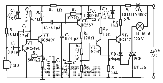
The circuit utilizes condenser microphones to detect sound and convert it into signal variations. This signal is then processed through directly coupled transistors VT1 and VT2, which form an amplification stage before being fed into a switching circuit. The...
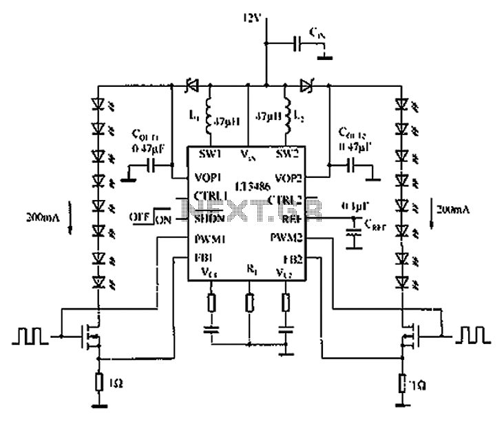
The automotive LED driver circuit diagram utilizes the LT3486. The LED is employed in the car's central high-mounted stop lamp (CHMSL), providing advantages such as faster achievement of the set brightness, higher efficiency, longer lifespan, and simplified design and...
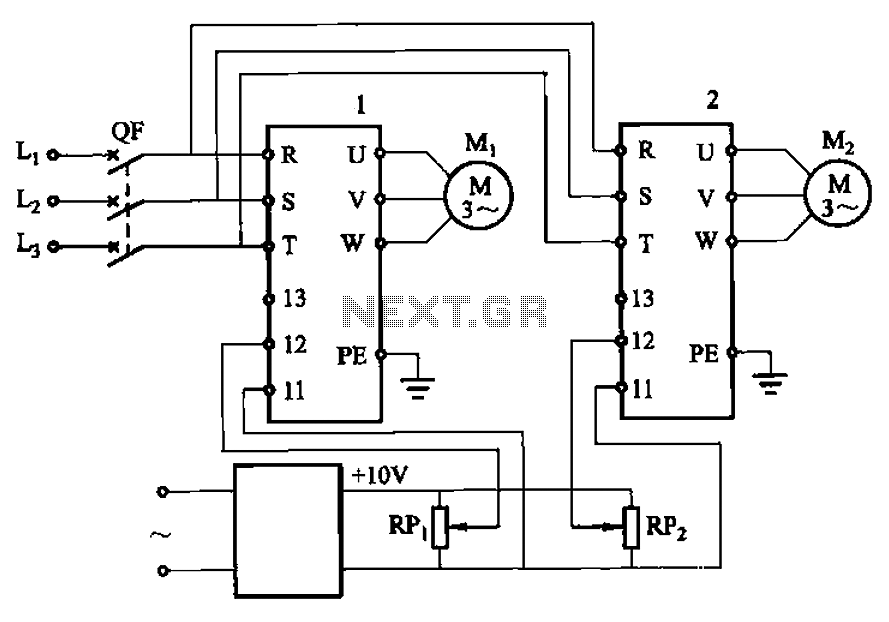
Adjust the potentiometers RPi and RPz to modify the speed of two motors. The circuit utilizes two potentiometers, designated as RPi and RPz, to control the speed of two separate motors. Each potentiometer is connected in a voltage divider configuration,...
An AC-DC power supply without a power switching circuit is typically utilized for lighting load circuits. Once the power grid is restored, the standby power supply automatically switches on. An automatic switching circuit using a transistor is implemented, with...
A highly versatile switch that can be controlled from any channel on a typical Futaba or JR radio setup. This switch was designed to trigger the shutter on digital cameras without the need for a servo attached to the...
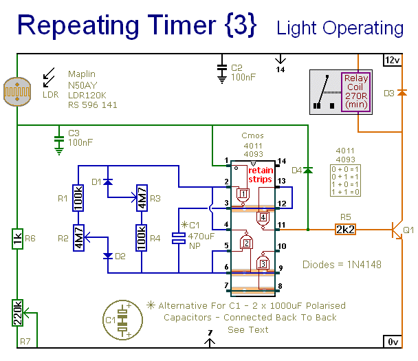
This circuit closely resembles Repeating Timer No. 2. However, the inclusion of a light-dependent resistor (LDR) allows the timer's operation to be confined to daylight hours. Resistor R7 enables the adjustment of the light level at which the timer...