
Remote flash trigger

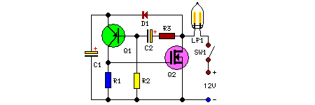
The light-activated silicon-controlled rectifier (LASCR) is a specialized electronic component designed for applications requiring light sensitivity, particularly in triggering circuits. The device operates by utilizing a small lens that captures incoming light, which subsequently activates the gate of the LASCR. This activation allows current to flow from the anode to the cathode, enabling the device to function as a switch in electronic circuits.
To implement this circuit effectively, a 6-inch length of stiff wire is recommended for the anode and cathode connections. This wire should be securely connected to a polarized power plug, ensuring compatibility with the sync terminals of the electronic flashgun. The polarized design is crucial as it provides correct orientation, preventing potential damage to the circuit due to incorrect connections. It is imperative to connect the anode lead to the positive sync terminal, as this configuration is necessary for the proper operation of the LASCR.
In practical applications, the positioning of the LASCR is critical. The connecting wires should be bent in such a way that the lens of the LASCR directly faces the main flash source. This alignment maximizes the light exposure to the lens, ensuring reliable triggering of the remote unit. The LASCR will respond to the light pulse emitted by the flash, allowing for synchronization in photography or other light-activated applications.
Overall, the LASCR setup provides a robust solution for remote triggering, combining light sensitivity with electronic control, making it an invaluable component in various electronic flash systems. Proper attention to wiring, connections, and positioning will ensure optimal performance and reliability in circuit operation.Transistor Ql is a light-activated silicon-controlled rectifier (LASCR). The gate is tripped by light entering a small iens built into the top cap. To operate, provide a 6-in. length of stiff wire for the anode andcathodeconnections and terminate the wires in a polarized power plug that matches the sync terminals on your electronic flashgun (strobelight). Make certain the anode lead connects to the positive sync terminal When using the device, bend the connecting wires so the LASCR lens faces the main flash. This will fire the remote unit.
Related Circuits
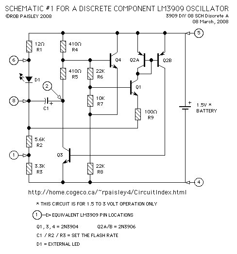
This page features a replacement circuit for the LM3909 LED Flasher / Oscillator using discrete components. The circuit is functionally the same as the integrated LM3909 but has a minor variation of the components used. Naturally the circuit will...
Access to the resistors was available, and measurements indicated an open circuit when disconnected from any ground or input source. The circuit in question involves resistors that have been verified for accessibility. When measured in isolation—meaning they are not connected...

This circuit utilizes three readily available 555 timer integrated circuits (ICs), all functioning as astable multivibrators. The first 555 timer has both an on period and an off period of 1 second. This IC regulates the on/off intervals of...
The LED is a fascinating component for amateur electronics hobbyists. The primary characteristic of an LED is that it requires a minimum of 3 volts to illuminate. Various circuits have been discovered to drive an LED using a single...
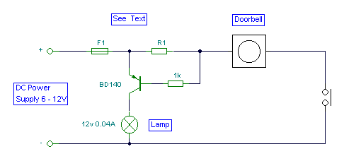
It is easy to miss the sound of a doorbell while watching TV. This circuit addresses the issue by providing a visual indication, such as a lamp or an LED. Connecting a lamp directly in parallel with the doorbell...
This remarkably straightforward circuit enables the operation of one or two robust 12V 21W car bulbs in a flashing mode using a power MOSFET. Such devices are especially suitable for road, traffic, and yard alerts, as well as in...