
Remote Thermometer circuit

The circuit comprises two main sections: the transmitter and the receiver. The transmitter section utilizes IC1, a precision centigrade temperature sensor, which provides an analog output voltage that is linearly proportional to the temperature. The output of IC1 is 10 mV per degree Celsius, which means at 20°C, the sensor outputs 200 mV.
This output voltage is fed into IC2, a voltage-to-frequency converter. This component is crucial as it transforms the analog voltage into a frequency signal. The conversion is designed such that an input voltage of 10 mV results in an output frequency of 100 Hz. Therefore, the output frequency can be calculated by multiplying the temperature in degrees Celsius by 10 Hz. For instance, at 25°C, the output frequency would be 250 Hz.
The frequency output from IC2 is then transmitted through the mains supply cables, utilizing the existing infrastructure for signal propagation. This method allows for a simple and effective means of transmitting the temperature measurement without the need for additional wiring.
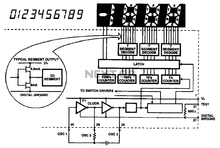
In the receiver section, a frequency counter is employed to detect the frequency bursts transmitted through the mains. This section counts the frequency pulses and translates them into a readable format displayed on three 7-segment LED displays. The least significant digit is dedicated to representing tenths of a degree, allowing the circuit to display temperatures in the range of 00.0 to 99.9 °C.
The design of the circuit ensures that it is capable of providing precise temperature measurements with minimal interference, utilizing the mains supply for signal transmission and maintaining a user-friendly display for easy reading of temperature data.This circuit is intended for precision centigrade temperature measurement, with a transmitter section converting to frequency the sensor`s output voltage, which is proportional to the measured temperature. The output frequency bursts are conveyed into the mains supply cables. The receiver section counts the bursts coming from mains supply and shows the counting on three 7-segment LED displays.
The least significant digit displays tenths of degree and then a 00.0 to 99.9 °C range is obtained. IC1 is a precision centigrade temperature sensor with a linear output of 10mV/°C driving IC2, a voltage-frequency converter. At its output pin (3), an input of 10mV is converted to 100Hz frequency pulses. Thus, for example, a temperature of 20°C is 🔗 External reference
Related Circuits
The AC input circuit functions as a converter, transforming an alternating current (AC) signal into a direct current (DC) signal, which is subsequently processed by an analog-to-digital (A/D) converter chip. The input circuit is designed to handle AC signals, typically...

The circuit operates by processing an input signal through IC1-1 and a fourth-order low-pass filter, which provides a slope of 24 dB/octave with a cutoff frequency (fc) of 70 Hz and an amplification of 8.2 dB. The output from...
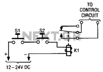
The simple two-hand safety control switch consists of two pushbutton switches connected in series; both must be depressed to energize the relay. The two-hand safety control switch is designed to enhance safety in applications where the operation of machinery or...
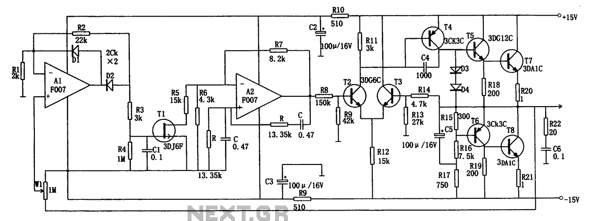
The low-frequency signal generating circuit demonstrates excellent performance characterized by stable operation, high output power, and minimal waveform distortion. It serves as an ideal source for low-frequency measurement signals. The circuit includes an operational amplifier (A) with a feedback...

The motion sensor circuit depicted in Figure 1 operates when a 12-volt power supply is applied to the input point. The motion sensor circuit is designed to detect movement and trigger a response based on the presence of motion...

A Variable DC Power Supply is an essential tool for electronics hobbyists. This circuit is not entirely new, but it is simple, reliable, robust, and short-proof, offering variable voltage up to 24V and variable current limiting up to 2A....