
Replacing Crystals and Ceramic Resonators with Silicon Oscillators

Silicon oscillators serve as an effective alternative to traditional crystal and ceramic resonator clock circuits, particularly in microcontroller applications. These oscillators are integrated circuits that generate clock signals through internal oscillation mechanisms, offering several advantages over their counterparts.
One significant benefit of silicon oscillators is their compact size. Unlike crystal and ceramic resonators, which require additional space for mounting and may necessitate specific PCB layouts to accommodate their physical dimensions, silicon oscillators can be designed in smaller packages, thus optimizing board space. This is particularly advantageous in applications where space is at a premium.
Another advantage is the improved temperature stability that silicon oscillators provide. While crystal and ceramic resonators can experience frequency drift due to temperature fluctuations, silicon oscillators can be engineered to maintain consistent performance across a wider temperature range. This reliability is crucial for applications that operate in varying environmental conditions.
Additionally, silicon oscillators often feature lower power consumption compared to traditional resonators. This characteristic is essential for battery-operated devices, where energy efficiency is paramount. The reduced power requirements of silicon oscillators contribute to longer battery life and overall enhanced system performance.
Furthermore, silicon oscillators offer greater flexibility in frequency selection. Designers can easily adjust the output frequency by changing the internal configuration of the oscillator, which allows for rapid prototyping and customization for specific applications. This adaptability is not as straightforward with crystal and ceramic resonators, which are typically fixed-frequency devices.
In summary, the transition from crystal and ceramic resonators to silicon oscillators in microcontroller clock applications presents several technical advantages, including reduced size, improved temperature stability, lower power consumption, and enhanced frequency flexibility. These factors make silicon oscillators a compelling choice for modern electronic designs.A short note describing how to replace crystal and ceramic resonator clock circuits with silicon oscillators and highlighting some of the technical advantages offered by these devices in microcontroller clock applications.. 🔗 External reference
Related Circuits
On following pages circuits are shown for 3rd overtone crystals 15 to 65MHz and 5th overtone crystals 60 to 105 MHz operating in their series resonant mode. In both of these circuits with the crystal short circuited, the oscillator...
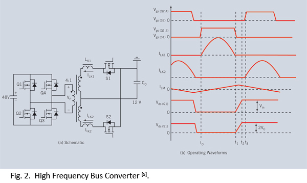
Distributed power systems are commonly used in telecommunications, networking, and high-end server applications, utilizing a 48 V bus voltage derived from the telecom industry. This 48 V bus supplies several isolated point-of-load (POL) converters that power the end loads,...
A linear feedback amplifier that incorporates reactive elements can produce sinusoidal oscillations at a frequency where the loop gain Ab equals -1. The sine wave oscillators examined in this experiment comprise two interconnected components: the amplifier section and the...
Original components, when still functional, exhibit stability and are not subject to infant mortality. Individual opinions may vary based on personal experiences. However, responses can differ due to several factors: the quality of the design utilizing appropriate components, the...
The circuit is designed exclusively for fundamental crystals, as it lacks mode suppression components. The oscillator transistor Q104 remains in a cutoff state for most of the time, activating only briefly during the peak of the crystal current waveform....
The use of a quarter-wave parallel-wire line as a tuning unit has been discussed in the chapter on Short-Lines, where it was pointed out that these circuits have comparatively high Q even at higher frequencies. Their significant length (approximately...