
Small TV terminal with ATmega8 microcontroller

The proposed circuit utilizes a microcontroller, specifically the ATmega8, as the central processing unit to manage data input and output. The microcontroller's architecture allows for efficient handling of the required data display, supported by a minimum of 1 kB of RAM to facilitate the rendering of a 40x25 character display. The communication between the microcontroller and the TV set is established through a video output that connects to the TV's AV input, ensuring compatibility with standard television equipment.
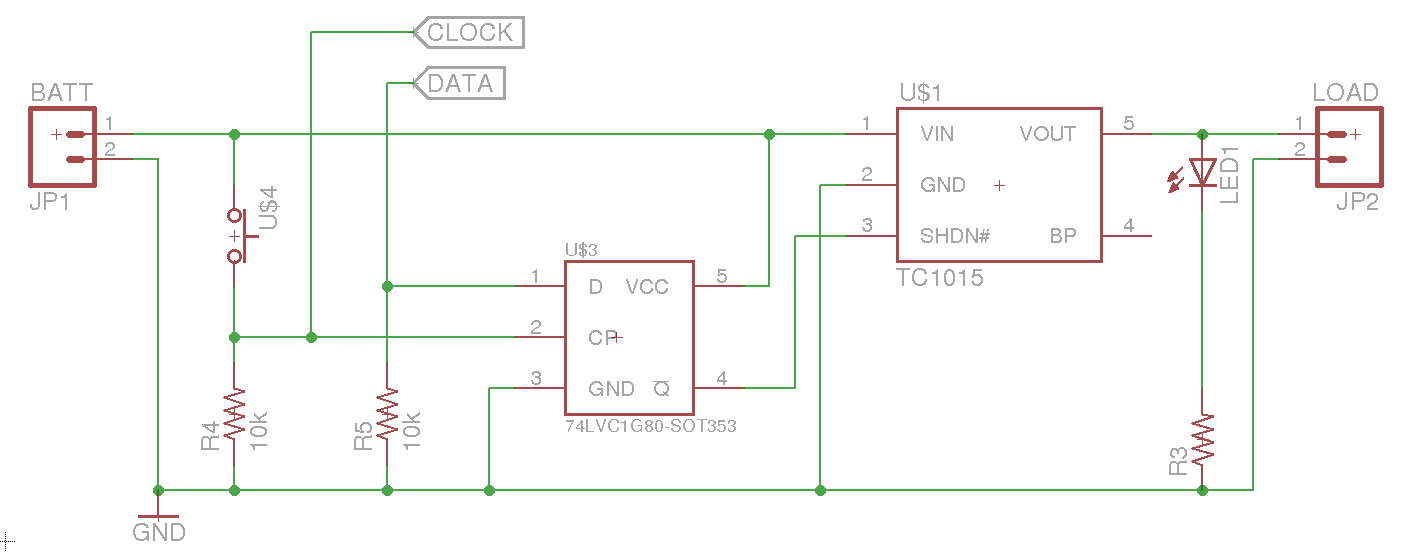
The power supply circuit is designed to accommodate both the built-in and standalone versions of the terminal. The standalone version features a voltage regulator to maintain a stable 5V output, essential for the microcontroller's operation. The RS232 to TTL converter, implemented with two transistors, serves to translate the communication signals from the microcontroller to a format compatible with the television and keyboard inputs. This design choice minimizes component count while ensuring reliable signal conversion.
For user interaction, the standard IBM PC keyboard provides an accessible and cost-effective solution. The keyboard interface allows for easy data input, leveraging the existing layout of characters without the need for custom mechanical designs. This approach not only simplifies the assembly process but also enhances the overall user experience by providing a familiar interface.
The assembly process involves careful soldering of components onto a printed circuit board (PCB), followed by thorough testing to ensure functionality. The program must be loaded into the microcontroller, with specific fuse settings configured to optimize performance. The circuit is designed to be robust, allowing for easy troubleshooting and modifications as necessary, making it suitable for hobbyists and engineers alike.When you use microcontrollers in your designs, sometime you face a problem how to show user required data. Several LEDs, 7 segment display or LCD module can be solution. But if you must show a lot of information simultaneously, it can be difficulty. Large LCD modules are expensive and graphic modules require complicated control. You can solve it with a help of PC. Just send data via serial line to the computer and display everything on computer`s display. But another user usually occupies computer or you need it for another job. :-) I have had to solve the same problem some time ago. I have chosen normal small TV set for that. A lot of families change TV in this time because of digital broadcasting or modern flat and slim LCD and plasma displays. So they put older TV set away and it is dormant somewhere. Or you can buy older TV very cheap. The display unit must be maximum easy. For data displaying is text mode with semigraphic mode sufficient. Just only 1 integrated circuit - microcontroller - must guarantee every function of the unit. A keyboard will be useful for data input. "Button by button" assembling of keyboard is complicated and mechanical design is a weak point in hobby construction.
Special keyboards are usually inaccessible or expensive. That`s why I have chosen standard IBM PC keyboard. PC keyboard solves as design as character variability - there are all characters on keyboard. Economic view is very advantageous and accessibility is almost unbeatable. The size is disadvantage of PC keyboard but beside TV set it doesn`t matter. I have developed 2 versions of TV terminal. "Built-in" version is designed for utilization in device. The second version is standalone device with external power source. TV terminal utilization is very easy. Connect video output to video (AV) input on TV set. Set communication speed on J1 jumpers. You can connect PC keyboard but it isn`t necessary. Turn terminal ON and display will show current parameters. The terminal is in full operation 3 seconds later. Schematic wiring is similar for both versions. You can find differences in the power supply part and in the serial line interface. Standalone version has got voltage regulator and simple RS232 to TTL converter. I have used only 2 transistors for logic voltage converter. Integrated circuit takes much more space. As you can see wiring diagram is very easy. Most of the functions are centred in the microcontroller U1. There must be minimally 1 kB RWM for 40x25 character screen. I have selected well-known and available type - ATmega8. Independency for every of these 3 processes was the most complicated task. Video signal must be generated utterly on the dot. Program was created in assembler and compiled code is here. Microcontroller clock is on maximum frequency - 20 MHz. Frequency 22 MHz would be better, but for reproducibility I accepted 20 MHz. This backtracking brings slight differences in the horizontal width of pixels. Forgive me - it is only hobby design (or maybe you will notice this never :-). The power supply voltage regulator and logic level converter are included in the standalone version. To keep circuit easy I selected (inspired by biprog) simple converter with 2 transistors. There is no problem with short serial line. But if you connect long wires with bigger capacity then communication can produce errors in higher speeds. Be careful with used keyboard. Consumption most of them is reasonable low, but there are types with consumption above 100 mA. High current causes overheating of U2 voltage regulator. Use voltage regulator 7805 in the TO220 case or reduce power supply voltage in this event. It is very easy to make both versions of TV terminal. Mount and solder every component to PC board. Check up complete device. The last operation is downloading program into microcontroller. Set fuses: RESET=ON, BROWN-OUT LEVEL 4. 0V, OSCILLATOR=EXT. CRYSTAL HIGH FREQ. Connect bui 🔗 External reference
Related Circuits
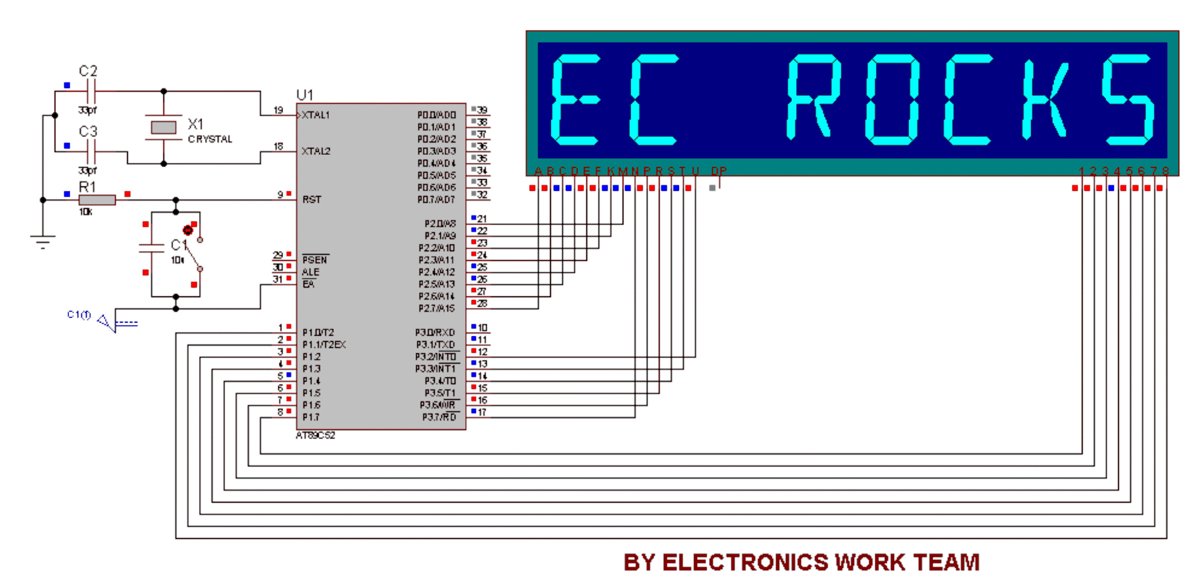
This circuit utilizes a 14-segment display to represent characters. The 14-segment display consists of 22 pins, which facilitate the display of various characters. Eight pins labeled A, B, C, D, E, F, K, and M are connected to the...

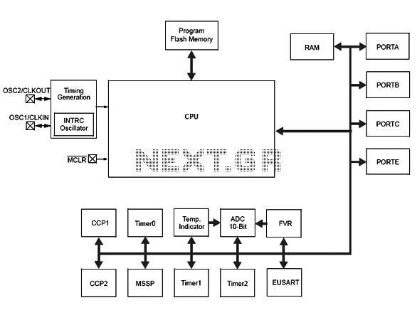
The Atmega8 microcontroller from Atmel features numerous digital and analog input/output lines, making it an ideal choice for developing various measurement equipment. It is essential to have the GCC AVR programming environment installed, as outlined in the article "Programming...
If an application utilizes a MOSFET to switch a load, it is straightforward to incorporate short-circuit or overload protection. This can be achieved by leveraging the internal resistance RDS(ON), which generates a voltage drop proportional to the current flowing...
Microchip has announced the availability of new PIC16F1512 and PIC16F151213 XLP microcontrollers. These new XLP (EXtreme Low Power) microcontrollers feature enhanced power management capabilities, making them suitable for battery-operated applications. The PIC16F1512 and PIC16F151213 microcontrollers are designed to operate with...
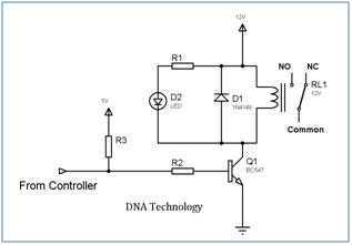
Relays are devices which allow low power circuits to switch a relatively high Current/Voltage ON/OFF. For a relay to operate a suitable pull-in & holding current should be passed through its coil. Generally relay coils are designed to operate...
A soft power switch for a microcontroller is designed such that a momentary switch can activate the circuit, including the microcontroller. When the switch is pressed a second time, the microcontroller is capable of shutting itself down after executing...