
revamping a vintage yamaha t 80 tuner
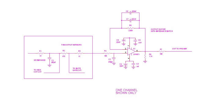
The T-80 output circuit schematic includes several critical components designed to enhance the overall performance of the tuner. The operational amplifier (op-amp) serves as a signal buffer, effectively isolating the tuner output from the load presented by the Jensen Audio Isolator. By employing a feedback network, the circuit ensures stable gain and minimizes distortion, which is particularly beneficial when interfacing with low impedance devices. The choice of resistors and capacitors in the feedback loop is essential for achieving the desired frequency response and maintaining linearity across the audio spectrum.
To further optimize the circuit, attention must be given to the placement and routing of traces on the PCB. Given the single-sided design, minimizing the length of signal paths and strategically placing ground connections can significantly reduce parasitic capacitance and inductance, thereby enhancing signal integrity. Implementing decoupling capacitors near the power pins of the op-amp can also help mitigate high-frequency noise and improve transient response.
The introduction of a high cut filter, although not always necessary, can be a valuable addition when dealing with particularly noisy signals. This filter can be implemented using additional capacitors and resistors to form a low-pass filter configuration, allowing for selective attenuation of unwanted high-frequency noise while preserving the integrity of the desired audio signal.
In conclusion, the modifications and enhancements made to the T-80 output circuit and grounding scheme demonstrate a comprehensive approach to improving the performance of FM tuners from this era. By addressing the inherent limitations of the original design and incorporating modern components and techniques, significant gains in audio quality and reliability can be achieved.Most FM tuners from this era suffer from two major problems. They have a high and reactive output impedance, and the grounding scheme inside the unit is at best dubious. This is a unit from the era when single sided boards where standard issue. The near total lack of ground plane and high impedance returns to the power supply are very much part of this unit.
One wonders what the performance might have been had Yamaha decided to use a double sided board with a fair amount of ground plane on the component side of the board. The following will show an approach to tackle both of these problems. The following schematic is of the T-80 output circuit and the buffer installed to lower the output impedance so I can drive a Jensen Audio Isolator, which is just a pair of Jensen line level transformers in a package.
Please note the feedback network from pin 2 to pin 6 of the op amp. The 2. 55k ohm resistor is the approximate resistance match of T-80 output circuit and the two capacitors in parallel represent the capacitance match of the T-80 output circuit. Although it is not shown here, when the T-80 has the high cut filter added the capacitance will double.
The high cut circuit is only activated when you find a very noisy station that is not coming in well in local mode. For my present antenna configuration I really don`t need this and the output circuit is optimized for local stereo mode.
This circuit will reduce upper order distortion, especially when connected to a relatively low impedance input and lower the output impedance to 100 ohms to drive the Jensen Audio Isolator. For technical information on the Jensen Audio Isolator Go Here: Although transformers certainly have some drawbacks, they are very effective in isolating the ground of one unit from another.
Given the grounding scheme used in the T-80, the use of the transformers has been very effective in reducing noise. They are not cheap, but many of us find the performance well worth it. When I received the tuner back from alignment at Stereo Surgeons in East Hartford CT. I noted many performance changes. Sensitivity, stereo separation, and distortion had definitely improved, but with the increase in sensitivity noise had also increased.
I went back to the schematics for further study, and also had a good long look at the board layout. I noted that all the 0. 01uf and 0. 022uf bypass caps in the RF and IF sections were ceramic disc caps, and after looking through some data sheets on class three ceramic disc caps I noted that aging characteristics on class three ceramic caps was somewhat similar to electrolytic caps. I decided to replace them with NPO ceramic caps. This may well be excessive for this application and in all probability the CKO5 series caps would do just fine.
So I will plead mea culpa to being a certifiably excessive here. I also added 0. 1uf bypass caps across the electrolytic capacitors in both the RF and IF sections. As I previously noted in this article the board layout is single sided and ground plane in the unit has been sacrificed to accommodate a single sided board. The main ground to the chassis appears to be a chassis support bracket that goes down between the RF section & the rest of the unit.
I added ground straps using 1/8 inch flat braid from the return of the power supply to the chassis. From the return of the power supply I added a ground strap that went to small ground plane near the audio output. From there a ground strap was connected to a small ground plane of the IF section. From that same ground plane in the audio output section I added another ground strap to ground plane next to the bracket.
The very last thing was to install a 75 ohm F pin connector for the RG6 cable run from the antenna. When the Yamaha T-80 was produced Yamaha used their own custom 75 ohm connector and these parts are no longer available. Note from the photo the short lead length down to the P. C. Board 🔗 External reference
Related Circuits
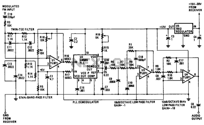
The operational amplifier (Op Amp) U1 and its associated components form a 67-kHz bandpass filter. A twin-T network, consisting of four 1100-ohm resistors and four 0.0022-microfarad capacitors, is integrated into the feedback loop of the op amp. This configuration...
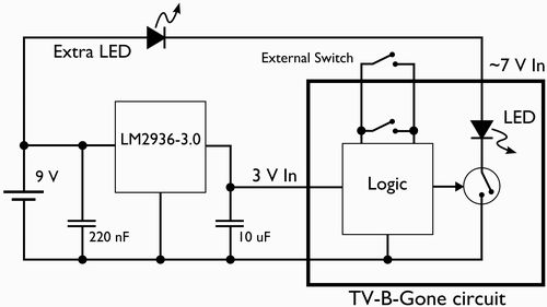
This document outlines the process of modifying a TV-B-Gone device to fit into the casing of a vintage television remote control. The original on/off button of the remote will be repurposed to activate the TV-B-Gone. Additionally, the power supply...

According to current legislation in many countries, vintage cars must also be fitted with a fog lamp at the rear. In modern cars, there is a bit of circuitry involved in the integration of fog lamps. Fog lamps are essential...
The circuit features an adjustable prestage utilizing the AF279 transistor, while the natural oscillation mixer stage employs the AF280 transistor. The power circuit is mounted on a board with copper coating. The main coil specifications are as follows: L1,...

Almost any receiver covering 540 kHz to 1600 kHz is suitable for broadcast band DXing, and there are a lot of them. But the antenna is another matter. If you are new to the hobby, or if you have...
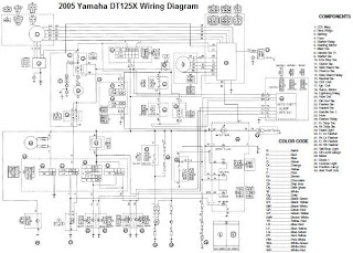
The electrical system of the 2005 Yamaha DT125X typically includes a CDI unit, battery, thermo unit, rectifier/regulator, servomotor, fuse, neutral switch, ignition coil, and main switch. The electrical schematic for the 2005 Yamaha DT125X outlines the interconnections and functionalities...