
Reversing motor drive dc control

The positioning servo drive circuit operates on the principle of feedback control to maintain the desired position of a mechanical element. The core components include a servo motor, a control circuit, and feedback sensors. The adjustments for balance, gain, and deadband are critical for optimizing the performance of the servo system to accommodate various operating conditions and loads.
1. **Servo Motor**: The servo motor is the actuator that moves the mechanical element to the desired position. It is typically a DC motor equipped with a feedback mechanism, such as an encoder or a potentiometer, to provide real-time position data.
2. **Control Circuit**: The control circuit processes the input signals and generates the necessary control signals for the servo motor. The circuit may include operational amplifiers for signal conditioning, and microcontrollers for more complex control algorithms. The gain adjustment allows for tuning the responsiveness of the system, while the deadband setting helps to prevent oscillations around the target position by introducing a threshold that must be exceeded before corrective action is taken.
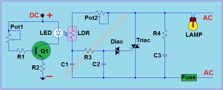
3. **Balance Control**: The balance control can be adjusted using a mechanical input or replaced with resistance transducers. The mechanical input allows for manual tuning of the system, while resistance transducers can provide automatic adjustments based on environmental factors such as light intensity or temperature variations. This adaptability enhances the versatility of the servo drive in different applications.
4. **Feedback Sensors**: Feedback sensors are integral to the operation of the servo drive. They provide continuous information about the position of the mechanical element, allowing the control circuit to make real-time adjustments. The choice of sensors, whether optical, resistive, or capacitive, can significantly affect the performance and accuracy of the servo system.
Overall, the described positioning servo drive is a sophisticated system designed for precise control in various applications, leveraging both electrical and mechanical inputs to achieve optimal performance.This is a positioning servo drive featuring adjustment of balance, gain, and deadband. In addition to control from a dc signal, mechanical input can be fed into the balance control, or that control could be replaced by a pair of resistance transducers for control by light or by temperature. the circuit shown.
Related Circuits
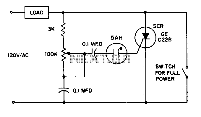
The 5AH will trigger when the voltage across the two 0 µF capacitors reaches the breakdown voltage of the lamp. Control can be obtained from full off to 95% of the half-wave RMS output voltage. Full power can be...
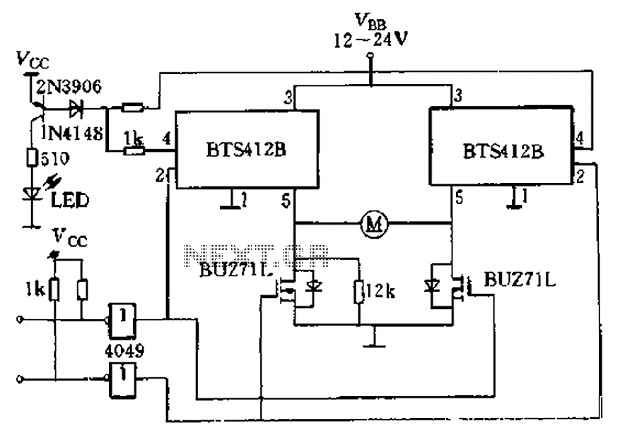
The BTS412B functions as two high-side power MOSFET switches, while two BU271L (50V, Zhang 1n) serve as low-side switches, forming a bi-directional H-bridge DC motor drive circuit. This configuration is designed for electrical automatic door systems, capable of handling...
Average vending machines are commonly found at railway stations, airports, fast-food restaurants, and even within companies. When a switch is pressed, the machine dispenses a cup of the selected beverage. Although this process appears straightforward, it involves complex logic,...
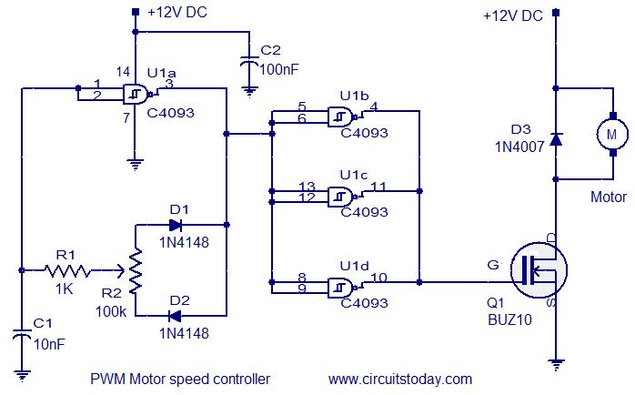
This circuit is designed based on a request from Mr. Vinoth in India. The requirement is for a 12V/5A DC fan motor controller. The circuit utilizes the quad 2-input Schmitt trigger IC CD4093 as its core component. Among the...
This is another AC light dimmer, with the primary distinction being that its control circuit is isolated from the AC line, making it much safer to use. The circuit can operate on both 120V and 220V AC lines. Note:...

Author Mazi Hosseini describes a simple, low-cost voltage-controlled current source using two operational amplifiers that provides a good range of current and maximum load. The circuit described by Mazi Hosseini utilizes two operational amplifiers (op-amps) to create a voltage-controlled current...