
RF AGC with Digital Control

The Automatic Gain Control (AGC) circuit plays a crucial role in ensuring consistent signal levels in communication systems. By automatically adjusting the gain of a signal, the AGC helps to maintain a stable output voltage despite variations in input signal strength, which can occur due to environmental factors or changes in signal sources.
In a typical AGC circuit operating at 50 MHz, a combination of analog components and digital control mechanisms is employed. The circuit may include a high-frequency amplifier, a rectifier to convert the AC signal to DC, and a low-pass filter to smooth the output. The digital signal that sets the output voltage can be generated by a microcontroller or digital signal processor (DSP), which responds to the detected signal strength and adjusts the gain accordingly.
The AGC circuit's design must consider several parameters, including the desired range of gain adjustment, response time to signal changes, and the overall bandwidth of the system. Additionally, the circuit may incorporate feedback loops to enhance stability and performance, ensuring that the output remains within specified limits even under varying conditions.
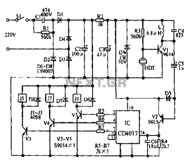
Overall, the AGC is a vital component in enhancing the reliability and quality of communication systems by providing automatic adjustments to signal levels, thus improving the overall performance of the system.The AGC is used in many system especially communications. This AGC? works at 50Mhz, and the output voltage is set by a digital signal that is needed by. 🔗 External reference
Related Circuits
The F84 MRTC was my second design of a miniature real-time controller. This version uses PIC16F84 running with a low power X-tal 32,768Hz. The scheduler for 6-channel output was saved in EEPROM. No terminal for serial downloading of the...
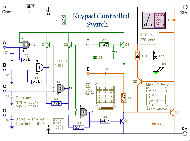
This is a universal version of the four-digit alarm control keypad. The design has been modified to free up the relay contacts, allowing the circuit to function as a general-purpose switch. A single pole changeover (SPCO) or single pole...
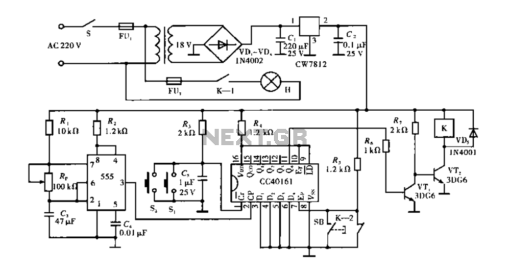
Corridor counter delay circuit for controlling lights. This circuit is tested and functional. When the circuit is energized, the 555 oscillator starts to oscillate. The CC40161 is cleared, and an integrating circuit composed of R3 and C5 transitions the...
The Slave Flash Trigger is activated by pressing a push button. When activated, the indicator lamp emits one to three flickers to indicate the programmed mode. One flicker means the flash will fire with each flash, two flickers indicate...
For normal use it is necessary to connect the battery when the jumper is connected. Please take care that the transmitter is on and the throttle is set to "power off". More: * switch on the transmitter, throttle to...
Fans can be controlled remotely with a switch that allows for speed adjustments, and this remote control can also be integrated with other household switches. Its primary feature is the use of a sub-transmission ultrasonic transmitter, which operates without...