
RF amplifier and filter for 10.7 MHz
The RF amplifier circuit operates at a frequency of 10 MHz, where the characteristics of the power MOSFETs play a critical role in performance. As the frequency increases, the capacitance of the MOSFETs becomes significant, leading to challenges in achieving noiseless feedback through transformer coupling. This effect can introduce intermodulation distortion and harmonic overtones due to capacitance variations with voltage, which necessitates careful selection of MOSFETs with high channel resistance and low capacitance.
The input IP3 of +45 dBm indicates that the amplifier can handle strong input signals without significant distortion, making it suitable for use in RF applications. The design includes two transformers, TR8 and TR10, which are essential for signal coupling. Both transformers are constructed from the same ferrite core material, ensuring consistent performance characteristics. The winding configurations are designed to optimize the coupling and minimize losses, with the gate transformer having a specific turn ratio to match the impedance of the MOSFET gate.
The inclusion of a 10.7 MHz bandpass filter is critical for rejecting unwanted signals, particularly harmonics and mirror frequencies that could interfere with the desired signal. The filter is designed to maintain a flat frequency response over a bandwidth of approximately 500 kHz, effectively suppressing the mirror frequency of 15.7 MHz by more than 80 dB. The notch filter at this frequency is particularly important as it prevents the introduction of intermodulation products that could arise from strong signals.
Overall, the RF amplifier circuit is designed to provide robust performance in a challenging RF environment, with considerations made for intermodulation distortion, frequency response, and signal integrity. The use of carefully selected components and transformer design ensures that the amplifier meets the stringent requirements of RF applications.The RF amplifier is similar to the one used in the 2. 5MHz amplifier. At a frequency of 10MHz the capacitances of a power MOS-FET become significant. Noiseless feedback by the use of transformers is no longer straightforward. Intermodulation and overtones are caused by the variation of the capacitances with the voltage. Performance is adequate if a MOS-FET with high enough channel resistance is selected (with associated small capacitances). The input IP3 of the RF amplifier is in the order of +45dBm which is high enough to make the 10. 7 to 2. 5MHz converter dominated by IM3 from the mixer. The entire unit has an input IP3 of about +40dBm. The gate transformer, TR8, is wound on a ferrite toroid core from Ferroxcube (Philips). Material 4C65, type TN 14/9/5. The gate winding is 6 turns, the source winding is 3 turns and the input winding is 7 turns. The wire dimension is uncritical. The drain transformer, TR10, is wound on a ferrite toroid core from Ferroxcube (Philips). Material 4C65, type TN 14/9/5. The winding is 6 turns with three twisted wires. The wire dimension is uncritical. The 10. 7MHz band pass filter has a flat response over about 500 kHz. The frequency response is shown in figures 2 and 3. The main purpose of the 10. 7MHz filter is to suppress the mirror image 2. 5 MHz above the local oscillator. Since the mixer is sensitive at harmonics of the local oscillator, higher frequencies also have to be well suppressed. The mirror frequency (15. 7MHz) is suppressed by more than 80dB. There is a notch filter at this frequency, without the notch the mirror frequency would have been attenuated only by about 65dB.
The notch is made with low cost standard inductors. They form resonators at 15MHz so they do not produce third order intermodulation problems for strong signals at 10. 7MHz. The 10. 7MHz receiver is intended as an IF unit. The unit in front of it is responsible for suppressing signals at the undesired responses of the 10. 7MHz unit. Undesired responses several MHz away from the desired passband will easily be suppressed by an additional 40dB to provide a mirror image rejection in excess of 120dB.
Feeding very strong signals at 13. 2 and 15. 7 simultaneously to the unit may give third order intermodulation products within the desired passband due to the non-linearities of the 2. 2 microhenry inductor in the notch filter. This is another reason why stages in front of the 10. 7 MHz unit should suppress 15MHz by at least 40dB. The 10. 7 MHz bandpass filter uses T80-6 toroid cores from Amidon. The resonant winding is 12 turns of 0. 8 mm enameld wire on all three cores, TR11, L24 and TR12. The input winding on TR11 as well as the output winding on TR12 is 4 turns of 0. 5 mm wire. 🔗 External reference
Related Circuits
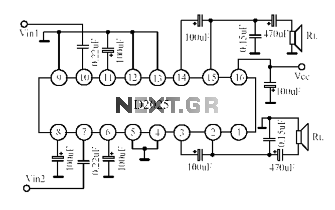
The D2025 is a dual audio power amplifier circuit designed as a stereo audio power amplifier integrated circuit. It comes in a DIP16 package and is applicable for various portable devices, such as tape recorders or portable stereo systems....
The aim of this design was to reproduce a Combo amplifier of the type very common in the sixties and the seventies of the past century. It is well suited as a guitar amplifier but it will do a...
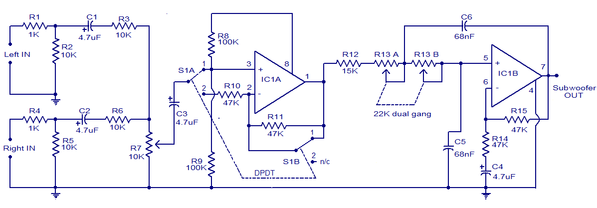
The circuit diagram depicts a simple subwoofer filter that operates on a 12V DC supply, making it particularly useful for automobile subwoofer applications. This circuit functions as a low-pass filter, with an adjustable pass frequency ranging from 60 to...
This audio bandpass filter is useful for amplification and filtering of weak AM TV video carriers. For example, a DFM (digital frequency audio multimeter) may have insufficient input sensitivity for measuring extremely weak SSB TV video audio signals. By...
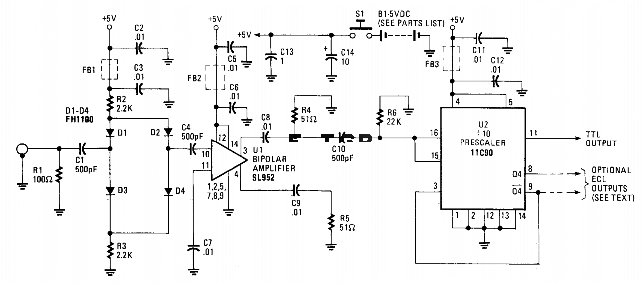
The 650 MHz prescaler probe's input is terminated by resistor R1 and is fed through C1 to the diode limiter composed of diodes D1 through D4. These diodes are forward-biased by the +5 volt supply for small input signals...
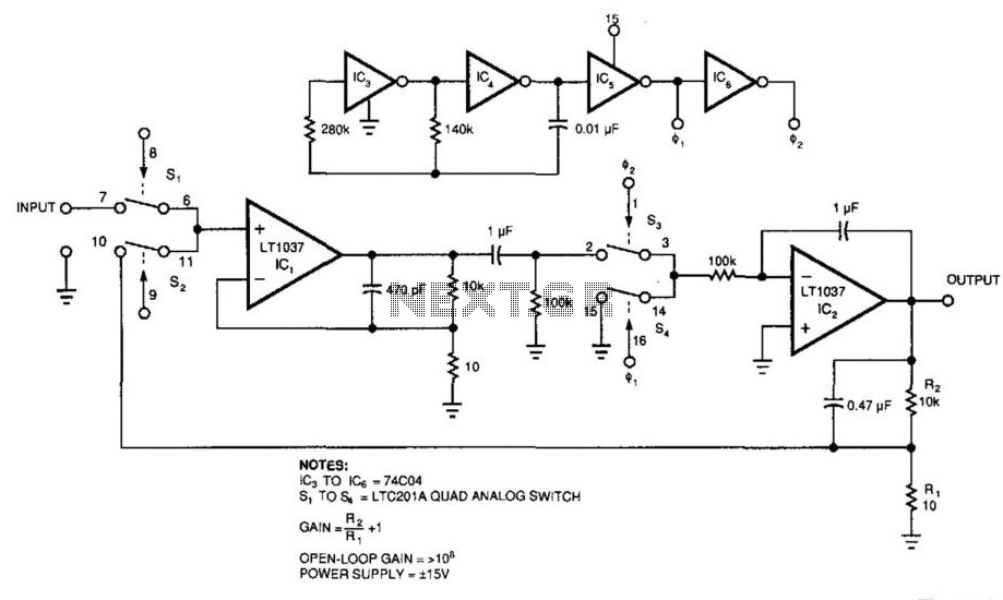
Figure 39-2's circuit combines a low-noise operational amplifier, IC1, with a chopper-based carrier-modulation scheme to achieve a low-noise, low-drift DC amplifier whose performance exceeds any currently available monolithic amplifier. The amplifier's offset is less than 1 mV, and its...