
rf field strength meter circuit

The RF Field Strength Meter Circuit is designed to measure the strength of radio frequency (RF) signals in the environment. This circuit typically consists of several key components including an RF detector, an operational amplifier, and a display unit, which can be an analog meter or a digital readout.
The RF detector is responsible for converting the incoming RF signal into a measurable voltage. This is often achieved using a diode or a specialized RF detector IC, which rectifies the RF signal and provides a corresponding direct current (DC) output proportional to the signal strength. The output from the detector is usually very low, requiring amplification.
An operational amplifier (op-amp) is employed to amplify the detected signal to a usable level. The op-amp configuration can be set up as a non-inverting amplifier to ensure that the output remains in phase with the input, thereby retaining the signal characteristics. The gain of the op-amp can be adjusted by selecting appropriate resistor values in the feedback loop, allowing for calibration of the meter to suit different measurement ranges.
The final stage of the circuit is the display unit, which translates the amplified signal into a human-readable format. In analog designs, a simple moving coil meter may be used, while digital circuits might employ an analog-to-digital converter (ADC) to provide a numerical readout. The choice of display type can affect the circuit's complexity and the ease of interpreting the results.
Power supply considerations are also critical; the circuit typically requires a stable DC voltage source to operate effectively. Battery operation is common for portable RF field strength meters, while mains-powered designs may incorporate voltage regulation to ensure consistent performance.
Overall, the RF Field Strength Meter Circuit is an essential tool in various applications, including telecommunications, broadcasting, and RF engineering, allowing users to assess signal quality and troubleshoot RF-related issues effectively.Good information about RF Field Strength Meter Circuit. You can learn and download RF Field Strength Meter Circuit online here.. 🔗 External reference
Related Circuits
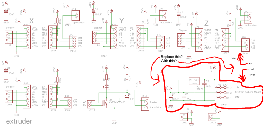
Preparing to assemble Adrian's Pololu stepper driver circuit has raised a question. He indicates that if using 5V from the Arduino Mega, the 78L05 voltage regulator should be omitted. This is a positive development, although there is an incorrect...
The function of the sound level display circuit is to enhance the appearance of an amplifier circuit or a radio player. It provides an impressive visual representation of audio levels. The sound level display circuit serves as a visual indicator...
The 555 circuit can be re-triggered if the input is held low for a duration longer than the output pulse. To prevent this from occurring, an additional timing circuit has been incorporated, consisting of a 1 Megohm resistor and...
The primary issue with the design of a stereo amplifier that includes a total bass driver is that the signals from the left and right channels eventually become combined. This summation process minimizes the separation between channels, compromising the...
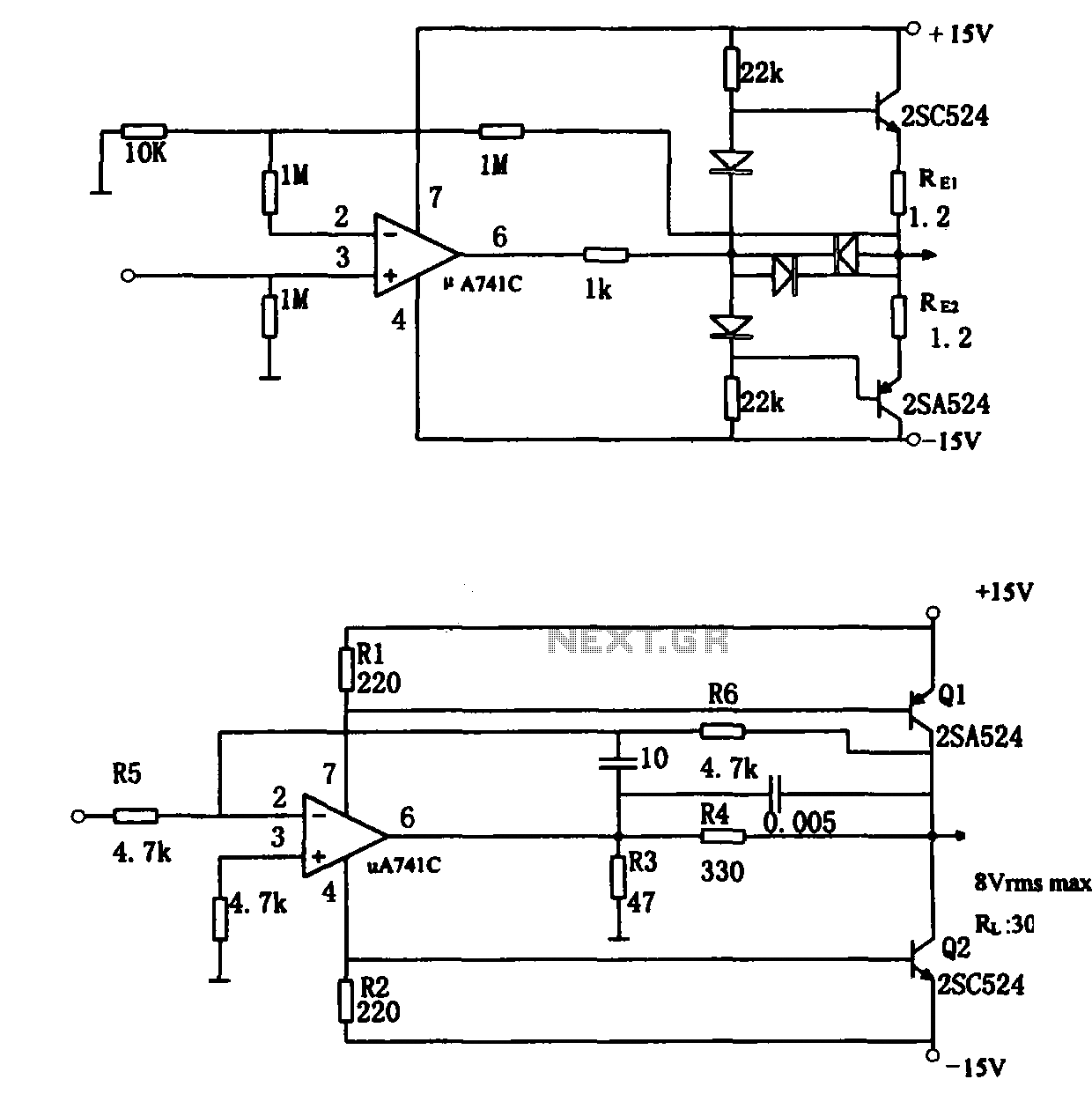
The direct coupling audio power amplifier utilizes an integrated operational amplifier. There are typically two practical configurations. The first configuration, depicted in (a), features a circuit structure that includes the output of the operational amplifier and a complementary symmetry...
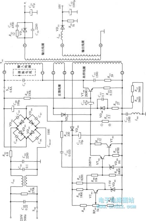
A high voltage switching stabilized voltage supply circuit is illustrated in the diagram. This is the switching power supply for an 80P type color television. It utilizes auto-excitation and a PWM circuit. The output is isolated from the power...