
Switch De-Bouncer Circuit

The described 555 timer circuit operates in a monostable mode, where it generates a single output pulse in response to a triggering event. The additional timing circuit, comprising a 1 Megohm resistor and a 47nF capacitor, serves to mitigate the risk of unintended retriggering of the 555 timer. This is particularly important in applications where precise timing is critical, as it ensures that the timer output pulse duration remains stable and predictable.
Upon pressing the switch, the capacitor charges rapidly, creating a negative pulse at the input of the 555 timer. This pulse initiates the timer's output. The careful selection of the resistor and capacitor values is crucial; the 1 Megohm resistor provides a slow discharge path for the capacitor, while the 47nF capacitor determines the timing characteristics of the circuit. The voltage divider, consisting of the 10k and 1 Megohm resistors, plays a pivotal role in ensuring that the voltage at the input of the 555 timer remains below the retrigger threshold once the capacitor is fully charged.
When the switch is released, the capacitor discharges quickly through the 1 Megohm resistor, resetting the circuit and preparing it for the next triggering event. The output from the 555 timer can interface directly with TTL and CMOS logic circuits, making this configuration versatile for various digital applications. The design effectively balances responsiveness and stability, making it suitable for timing applications, pulse generation, and signal conditioning in electronic systems.The 555 circuit can be re-triggered if the input is held low longer than the output pulse. To prevent this happening, I have included a further timing circuit comprised of the 1Meg resistor and 47n capacitor. Normally, the 47n capacitor is discharged via the 1 Meg resistor. When the switch is pressed the capacitor quickly charges and provides a br ief negative pulse to the 555 input. When the capacitor is fully charged, the potential across the voltage divider formed by the 10k and 1Meg resistors is insufficient to retrigger the monostable. Releasing the switch quickly discharges the capacitor. The output of a 555 monostable is suitable for connecting to TTL and CMOS logic circuits. 🔗 External reference
Related Circuits
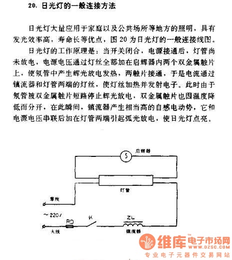
The general connection method for fluorescent lamps is utilized in residential and public lighting applications due to their luminous efficiency and long service life. The general wiring diagram for the lamp is illustrated in Figure 20. The working principle...

This circuit diagram represents a logic probe based on a single CMOS integrated circuit (IC). The logic probe indicates three conditions: High, Low, and Pulsing. Additionally, no LEDs will illuminate when the probe input is in a high-impedance state,...
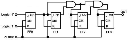
The circuit in Figure 1 is a 4-bit asynchronous counter, also known as a ripple counter. It consists of four J-K flip-flops with their J and K inputs connected to logic 1. This configuration causes the output of each...
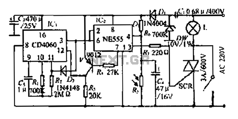
A photosensitive daytime electricity circuit utilizes a very small positive voltage. It features a 555 timer IC with four pins, including a reset pin that operates at low voltage. The circuit includes a bidirectional thyristor (iSCR) that controls lighting,...
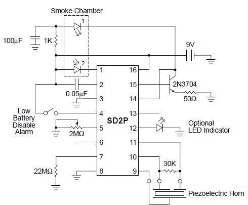
This smoke detector circuit diagram is based on the SD2 CMOS Photo-Electric Smoke Detector Integrated Circuit manufactured by Supertex Inc. It includes almost all the necessary components to build a simple and highly efficient smoke detector project. The LED...
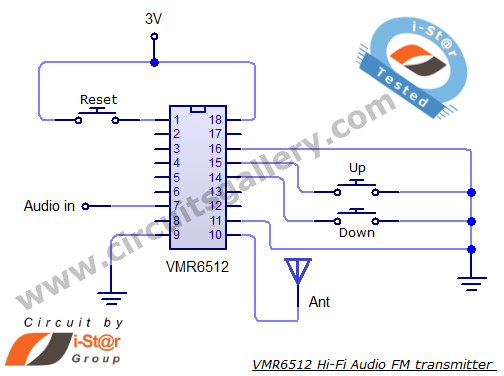
This article provides the circuit schematics for an FM transmitter along with the necessary explanations. The primary component utilized is the VMR6512 IC, a highly integrated FM audio signal transmitter chip designed for Hi-Fi audio applications. This chip can...