
Rf Output Indicator
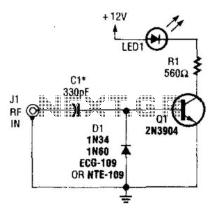
The RF detector circuit typically consists of a few key components: a diode, a resistor, a capacitor, and an LED. The diode acts as the primary sensing element, converting the RF signal into a DC voltage. This process is known as rectification. The output from the diode is then filtered using a capacitor, which smooths out the rectified signal, allowing for a stable voltage level that can be used to drive the visual indicator.
In this configuration, the resistor is connected in parallel with the LED to limit the current flowing through it, ensuring that the LED operates within its specified current range. The LED serves as the visual output, illuminating when an RF signal is detected, thus indicating the presence of RF energy.
The circuit can be powered by a low-voltage power supply, and the sensitivity can be adjusted by varying the values of the resistor and capacitor. This RF detector circuit is particularly useful in applications where monitoring RF output is critical, such as in transmitter systems, ensuring that operators can easily determine the operational status of the transmitter through a simple visual cue.
Additionally, the circuit can be enhanced by incorporating a variable gain amplifier to improve sensitivity or by using a microcontroller to process the signal further, providing more detailed information about the RF output. Overall, this RF detector circuit is a practical solution for visual RF signal indication. A simple RF detector circuit using a visual indicator can be useful for an RF output indicator, etc. This circuit was u sed for a transmitter ON indicator. 🔗 External reference
Related Circuits
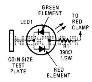
This circuit comprises a tri-color LED, a resistor, wire, and a coin-sized test plate. Two circuits must be constructed, one for each black clamp on a set of auto battery jumper cables. The circuits are installed inside the black...
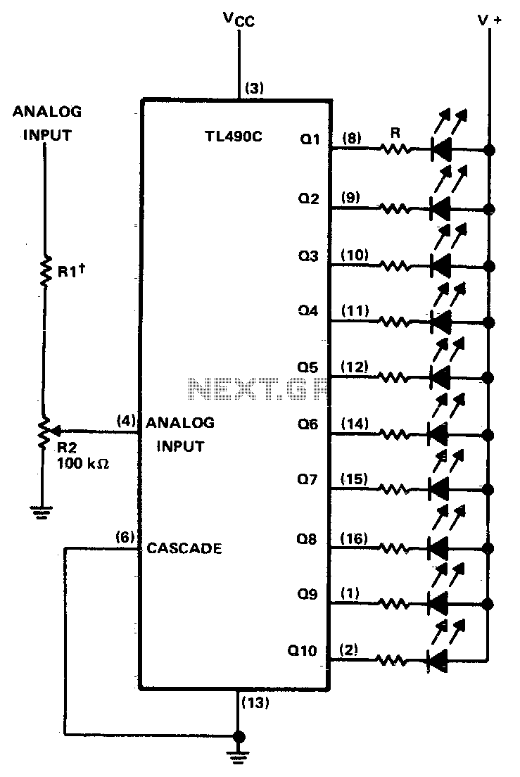
This ten-step adjustable analog level detector is capable of sinking up to 40 milliamperes at each output. The voltage range at the input pin should range from 0 to 2 volts. Circuits of this type are useful as liquid-level...
Game Show Indicator Lights (Who's First) Circuit The circuit below activates a light corresponding to the first of several buttons pressed in a Who's First game. Three stages are shown, but the circuit can be extended to include additional...
This indicator can be used, or see if your speakers can be damaged by the noise power. With P1 you can set the limit to which D1 LED lights. The pot is 100k here, you can even experiment with...
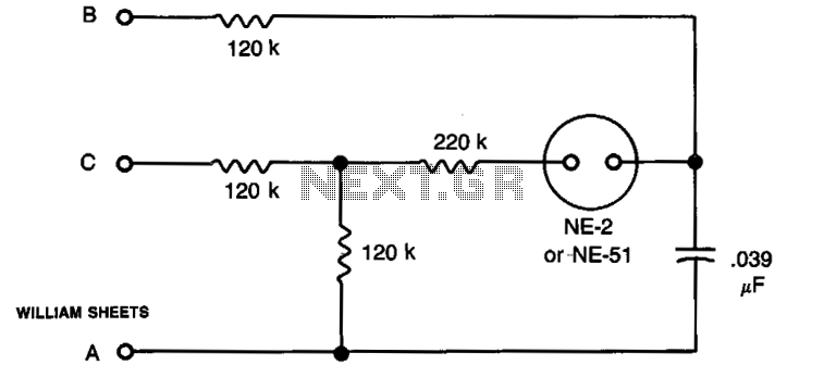
The circuit offers a straightforward method for identifying the phase sequence of a 3-phase 120 V source utilized in synchro applications. Terminals A, B, and C are connected to the three terminals of the source under examination. If the...
The circuit indicates that the phone is in use by illuminating a red LED. When the phone is not in use, a green LED lights up. It operates without requiring external power and can be connected at any point...