
Antenna Low Power RF & Wireless Connectivity
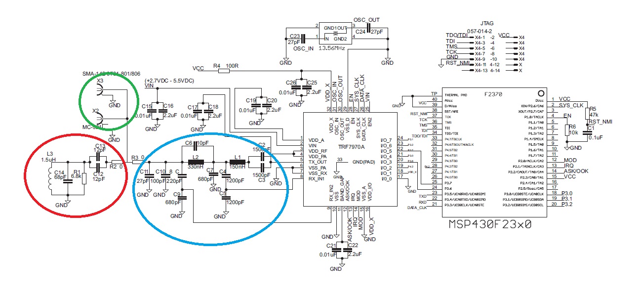
The TRF7970A antenna design involves careful consideration of component placement and impedance matching. The green area serves as the designated location for the antenna, ensuring proper connection through the 0-ohm resistors. The construction of the antenna is guided by the specifications provided in SLOA135, which details the necessary components and their arrangement for optimal performance. The red area plays a critical role in impedance matching, transforming the antenna's low impedance to a standard 50-ohm level suitable for RF instrumentation. This transformation is essential for ensuring that the antenna operates efficiently within the intended frequency range.
The inclusion of the red area allows for independent tuning of the antenna, which is particularly beneficial for circuit testing and validation. By providing a means to connect external instrumentation via the SMA connector, the designer can fine-tune the antenna characteristics using the adjustable capacitors and resistor. This flexibility in tuning is crucial for achieving desired performance metrics, such as gain, bandwidth, and efficiency.
When implementing the red area in the PCB design, attention must be given to the physical layout to minimize parasitic inductance. The proximity of the coil antenna to the tuning components (C1, C2) is vital; excessive lengths in the connections can adversely affect the circuit's performance. The layout should be optimized to ensure minimal interference and to maintain the integrity of the impedance matching.
In summary, the TRF7970A antenna design requires a systematic approach to component selection and placement, with particular emphasis on the roles of the green and red areas in the schematic. Proper implementation will facilitate effective antenna performance and reliable operation within the specified RF parameters.The "green area" is where should be placed the TRF7970A `s antenna (Between 0 ohm resistors, the antenna should be connected). TRF7970A `s antenna can be done step by step according to the document "Antenna Matching for the TRF7960 RFID Reader (SLOA135) ".
And here comes the part I do not understand: What role has the "red area" of the figure Why is placed that part of the circuitry in the schematic TRF7970A Why do not I see this part of the circuit in TRF7970EVM`s hardware Then, If Ibuild the TRf7970`s antenna as is shown in SLOA135 (3 capacitors, 1 resistor and antenna), I should do not include the "red area" in my hardware ciruit Why the intermediate 50 ohm To tune independently and in a easier way the antena without complicating the circuit. Also RF instrumentation is calibrated to 50 ohm. How you can do it Just unsolder R3_0(0 ohm shunt) to unconnect the blue part. Red area now can be connected to external instrumentation through the SMA connector(green area). Playing with C12, C13, C14, R1 and an impedance calculator you can tune it. I included also the red area in my hardware design. Until a while ago I did not know what the "red area" do Now, you explain me this: "Blue area that matches 50 ohm to 4 ohm".
If you have implemented the PCB with 3 capacitors (56, 47 and 10 pF) and a 1kohm you have implemented the red area. That is the red area. You do not need to include another red area if you can understand me. The L3 inductor represents only the antenna coil that is present in your PCB. The terminals of the PCB antenna coil should be connected to the terminals of the L3 inductor The last is a simpler approach that can enable the designer to match any coil antennas with simpler calculus.
With this approach if you unconnect the blue area and have the appropriate instrumentaion you can verify and measure PCB inductance very easy. just be carefull with the length of connection between the lumped components of the "red area". The coil antenna must be near as possible from the C1, C2, . The length of connection will introduce a serial parasitic inductance that must be accounted, and if you don`t get a very small length this can be responsible for the detunning of the circuit.
All content and materials on this site are provided "as is". TI and its respective suppliers and providers of content make no representations about the suitability of these materials for any purpose and disclaim all warranties and conditions with regard to these materials, including but not limited to all implied warranties and conditions of merchantability, fitness for a particular purpose, title and non-infringement of any third party intellectual property right. TI and its respective suppliers and providers of content make no representations about the suitability of these materials for any purpose and disclaim all warranties and conditions with respect to these materials.
No license, either express or implied, by estoppel or otherwise, is granted by TI. Use of the information on this site may require a license from a third party, or a license from TI. Content on this site may contain or be subject to specific guidelines or limitations on use. All postings and use of the content on this site are subject to the Terms of Use of the site; third parties using this content agree to abide by any limitations or guidelines and to comply with the Terms of Use of this site. TI, its suppliers and providers of content reserve the right to make corrections, deletions, modifications, enhancements, improvements and other changes to the content and materials, its products, programs and services at any time or to move or discontinue any content, products, programs, or services without notice.
🔗 External reference
Related Circuits
This project began with the exploration of arc starters that could be built at minimal cost using materials typically found in a tinker's workshop. Although it has been an enjoyable endeavor, the extensive collection of items in the basement...
The following diagram illustrates the circuit design of a 20W power amplifier built using the EL34 tube component. The EL34 is a well-known tube that is highly regarded for its performance in power tube amplifiers. The circuit presented is...
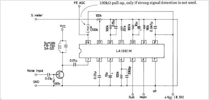
The LA1070 is an automatic gain control integrated circuit designed for use with automotive on-glass antennas. It is produced by Sanyo Semiconductor Corporation. The LA1070 operates by automatically adjusting the gain of the antenna signal to maintain a consistent output...
A low power FM pirate radio. The output power is approximately +35 dBm (3.16 watts) over a 50-ohm load and operates on a +24-volt power supply. The project consists of a Hartley oscillator (modulated VCO) and three stages (Class...

The circuit detailed in this document is designed to produce up to 30 kilovolts or more from a low-voltage DC source using a flyback transformer (LOPT) salvaged from a black-and-white or color television or computer monitor. With a typical...
A 12V switching power supply schematic has been observed to generate significant heat, which has prompted discussions among users in prominent forums, such as dp. The 12V switching power supply is a crucial component in various electronic applications, providing...
Warning: include(partials/cookie-banner.php): Failed to open stream: Permission denied in /var/www/html/nextgr/view-circuit.php on line 713
Warning: include(): Failed opening 'partials/cookie-banner.php' for inclusion (include_path='.:/usr/share/php') in /var/www/html/nextgr/view-circuit.php on line 713