
PLL FM demodulator LM565CN RC4558DN schematic

The FM demodulation circuit described employs the LM565CN, a versatile integrated circuit designed for frequency demodulation applications. The circuit operates at two specific frequencies, 10 kHz and 3 kHz, which are essential for effective demodulation of frequency-modulated signals. The differential amplifier A1 plays a crucial role in processing the incoming modulated signal. It generates two outputs, V1 and V2, which represent the demodulated signals. The function of A1 is to amplify the difference between the two input signals, ensuring that the output signals are properly displaced in amplitude for further processing.
Following the differential amplification stage, the outputs V1 and V2 are fed into an active low-pass filter (A2). The purpose of A2 is to remove unwanted high-frequency components, specifically targeting the pulsating component at 20 kHz that may interfere with the desired demodulated signal. The active low-pass filter is designed to allow frequencies below a certain cutoff frequency to pass while attenuating frequencies above this threshold. This characteristic is vital in ensuring that the output signals are clean and free from high-frequency noise, thus improving the overall quality of the demodulated output.
In summary, this circuit effectively combines differential amplification and active filtering to achieve high-quality FM demodulation, making it suitable for various applications in communication systems where signal integrity is paramount.Circuit is shown using 10kHz 3kHz LM565CN constitute the FM demodulation circuit. The V1 and V2 differential demodulation output diagram (b) of the differential amplifier A1 level displacement and amplification, and then by the A2 active LPF filtered pulsating component of 20kHz.
Related Circuits
Approximately 20 years ago, small key-holders that emitted an intermittent beep for a few seconds upon detecting a whistle were quite common. These devices utilized a specialized integrated circuit (IC) that made them unsuitable for home construction. The current...
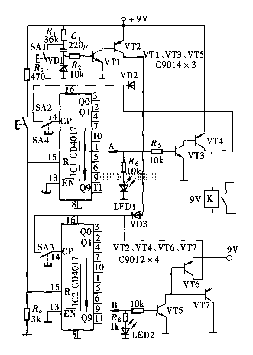
The circuit consists of a two and four decimal counter CD4017 used in conjunction with a password switch. It is composed of the output terminals from the key switch logic combination of components, which provide another feature of the...
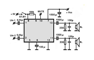
The amplifier circuit utilizing the STK4050 integrated circuit (IC) is known for its robustness and high quality. This article presents a 200-watt power amplifier circuit based on the STK4050. The circuit features an advanced auto wiring diagram with color-coded...
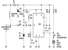
The sections available in this datasheet cover general design considerations for the 555 timer, frequently asked application questions (FAQ), design formulas, and examples of innovative applications. Examples of applications include a Missing Pulse Detector, Pulse Width Modulation (PWM), Tone...
When both S1 and R2 are activated, current flows through each of the lamps connected in parallel to the rheostat. The current flow, and consequently the intensity of illumination, can be regulated by adjusting the effective voltage from the...
Many individuals find that they sleep well in natural environments, such as tents or wooden huts. This phenomenon is attributed not only to the healthy surroundings but also to our subconscious ability to perceive the Earth's natural magnetic fields....