
Secure lock circuit (CD4017) schematic
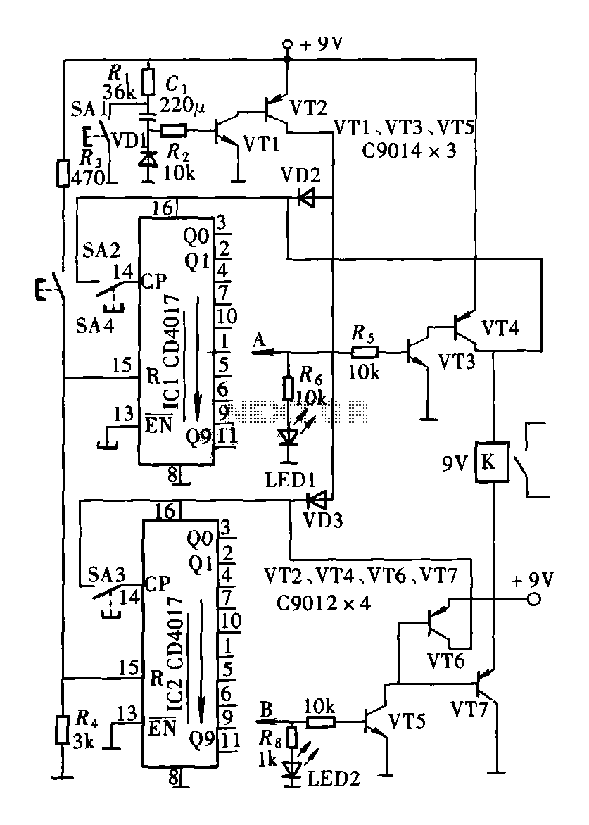
The described circuit employs the CD4017 decade counter IC, which is capable of counting from 0 to 10 and can be configured to produce outputs corresponding to each count. In this application, the CD4017 serves as the core component for the password entry system, where each key press corresponds to a specific output state.
The two CD4017 counters are connected in a manner that allows for the detection of a four-digit password. Each CD4017 counter outputs a high signal on its respective output pin when the count reaches a specific number. The password switch is implemented using a key switch mechanism that allows the user to input a sequence of digits. The logic combination of components ensures that only the correct sequence of key presses will activate the desired output.
The circuit design includes pull-down resistors to ensure stable logic levels at the inputs of the CD4017 counters. Additionally, debounce circuitry may be incorporated to prevent false triggering caused by mechanical bouncing of the key switches.
The output from the counters can be utilized to drive additional components, such as LEDs for visual feedback or relays for activating other devices upon successful password entry. The simplicity of the circuit makes it suitable for applications where basic access control is required, such as in security systems or electronic locks.
Overall, this password switch circuit demonstrates an effective use of the CD4017 decade counter in a straightforward electronic access control application.Circuit as shown by the two and four decimal counter CD4017 password switch composed by the output terminal of the key switch logic combination of components to another feature of the electronic code switch. Circuit is simple, and only two CD4017 four password input keys.
Related Circuits

This schematic represents a radio receiver circuit based on the TDA7088T, which is suitable for use in mono portable and pocket radios. The TDA7088T is a bipolar integrated circuit designed to operate with a minimal number of peripheral components...
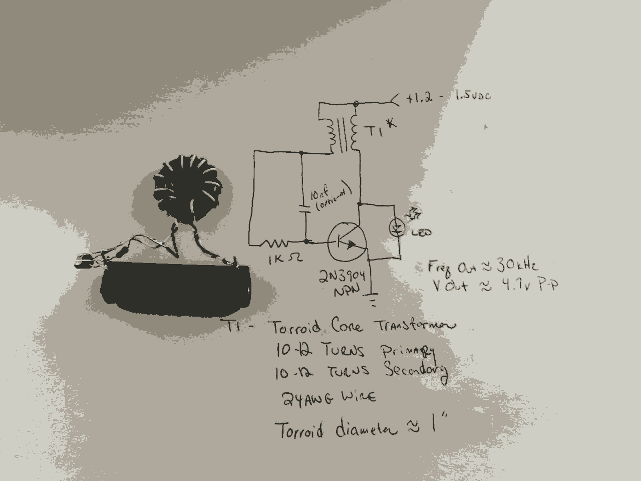
In the previous post, the primary principles of the switching power supply were discussed. Essentially, an oscillator drives a transformer with a ferrite core at a relatively high frequency, thereby minimizing the size, weight, and cost of power supplies....

This circuit is designed as a pocket-sized, high-performance audio oscillator. It can operate using a battery-powered version, which is feasible at a very low cost by utilizing a single quad op-amp to provide the entire active circuitry. The design...
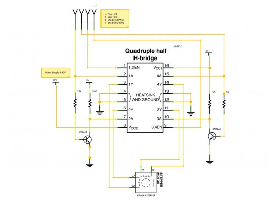
A stepper motor controller based on schematics available on the Arduino website. Initially, a two-pin configuration was attempted for a bipolar stepper motor, but it did not function as expected, especially with the library provided on the site. The...
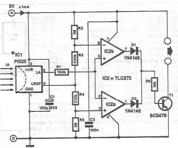
This infrared detector circuit is designed using the PID20 integrated circuit manufactured by Siemens, which converts thermal radiation into electrical impulses. It includes an operational amplifier and several electronic components. The output signal at pin 3 is compared with...
The following circuit illustrates the Weller WLC100 Electronic Soldering Station Circuit Diagram. This circuit utilizes the Q4012LPH Transistor. Features include safety measures, temperature control, and functionality as a soldering station that performs effectively for various applications. It is a...