
Using PLL Phase Locked Loop IC frequency N 1 to 10 of the multiplier circuit
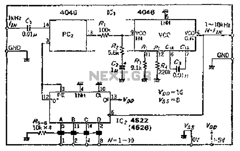
The CMOS 4046 PLL is a versatile integrated circuit designed for frequency synthesis and demodulation applications. The primary components of the 4046 include a phase comparator, a voltage-controlled oscillator (VCO), and a programmable frequency divider. The phase comparator can operate in two modes, PC1 and PC2, which allow for different applications depending on the desired output characteristics.
In operation, the VCO generates an output frequency that is adjustable based on the input control voltage. The programmable divider allows for the division of the VCO output frequency, enabling the PLL to lock onto a specific frequency ratio. The phase comparator continuously monitors the phase difference between the divided output frequency and the reference input frequency. When a phase discrepancy is detected, the phase comparator generates an error signal that is filtered by the loop filter (consisting of resistors and capacitors) to smooth out the control voltage applied to the VCO.
The loop filter's design is crucial for the stability and performance of the PLL. It determines the response time and bandwidth of the system, affecting how quickly the PLL can lock onto a new frequency. The choice of resistor and capacitor values in the loop filter must be carefully calculated to achieve the desired transient response and steady-state performance.
The VCO's frequency range is defined by the input voltage, which can be adjusted to cover a wide range of frequencies, making the 4046 suitable for various applications, including frequency modulation, demodulation, and clock recovery in communication systems.
Additionally, attention must be given to potential circuit errors that can arise from component tolerances, noise, and temperature variations. Implementing design strategies to mitigate these issues, such as using precision components and providing adequate thermal management, can significantly improve the long-term stability and reliability of the PLL circuit. C- MOSIC4046 PLL having the main function of a maximum operating frequency of iMHz integrated circuit, which is connected to the programmable divider, can constitute the input frequency increases t times the circuit. Phase comparator PC2 check, t phase 1 is equal to the frequency of the output of the frequency divider circuit and t which outputs ) ~ vP-P signal via the loop filter (roar -R2, G soap) after filtering vco oscillation frequency control. vco variable range of jf a field -f, In is from the input frequency fiv to N- ffw. Consider Journal circuit errors and long-term stability, actually increase the number of safety margin.
Related Circuits
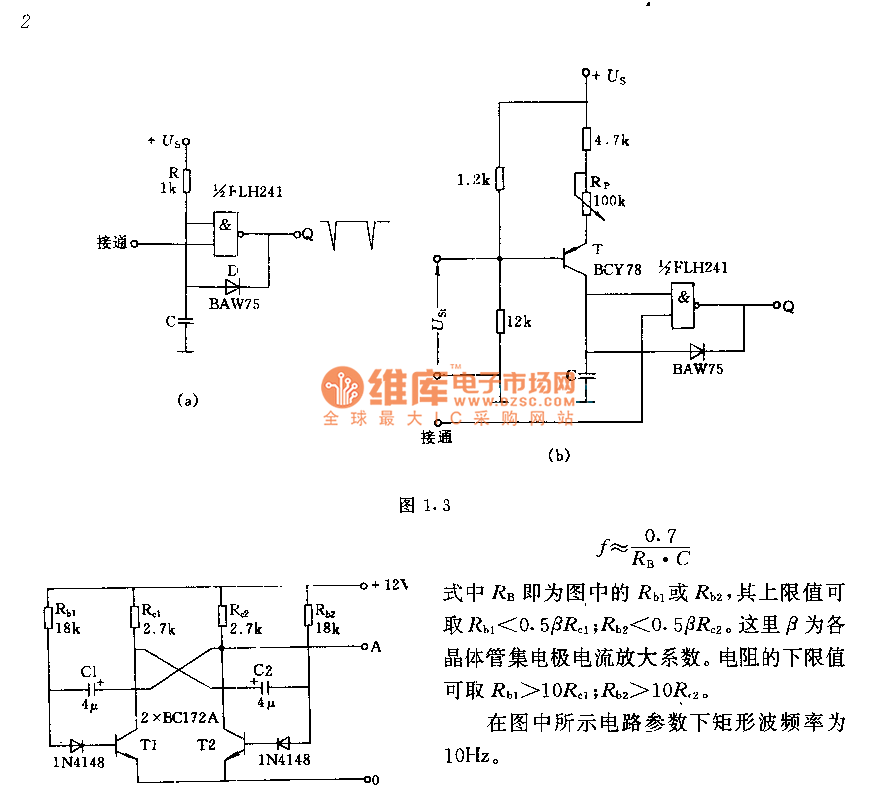
The circuit consists of two components whose parameters and models are designed to simultaneously generate a rectangular wave with a duty cycle of 1:1. The frequency is defined by the equation f = 0.7/(RB * C), where RB refers...
A simple transistor generator and transformer converts a 1.5V battery voltage to several hundred volts. This high voltage current then passes through a diode, which rectifies the current to DC. This DC current is stored in a relatively large...
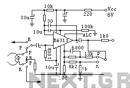
BA313 is a built-in automatic level control (ALC) circuit for audio recording preamplifiers, commonly used in cassette tape recorders. It is housed in a 9-pin dual in-line package (DIP) and features a wide range of automatic level control, operates...
The ZN414 is an economical, single-chip AM radio integrated circuit introduced in 1972 by Ferranti. The TDA7000 is a monolithic integrated circuit designed for mono FM portable radios or receivers, focusing on minimizing size. Additionally, there is an FM...
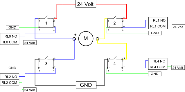
Eight solid-state relays (SSR) and an ADAM-4068 (Serial-I/O device) are utilized to wire a circuit for controlling a motor in a robotic application. The ADAM-6048 is a versatile device that facilitates control of digital inputs and outputs via RS-485...
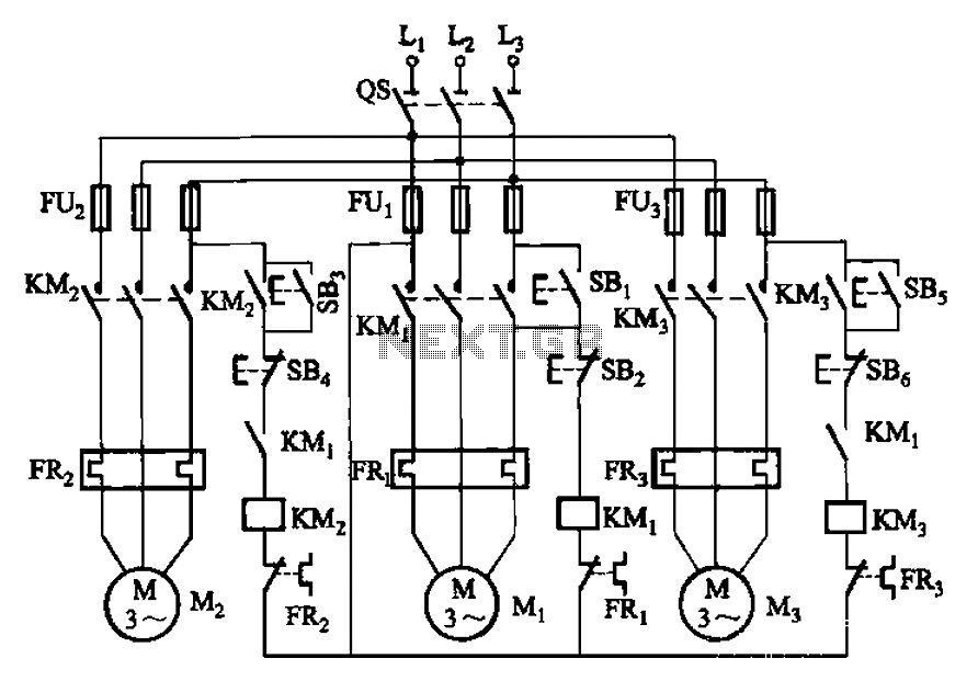
The circuit shown in Figure 3-89 illustrates a system where starting motor M1 allows motors M2 and M3 to initiate operation. Upon shutdown, motor Mz can be stopped first; however, once motor M1 is stopped (by pressing switch SB2),...