
Ne602 Direct Conversion Receiver Circuit
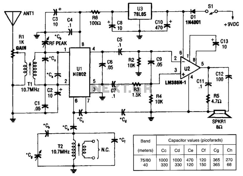
The NEC602 is a versatile integrated circuit that operates effectively in low-power applications. Its primary function as a mixer allows it to combine radio frequency (RF) signals with a local oscillator signal, resulting in a zero IF output. This configuration simplifies the design of the receiver by eliminating the need for additional filtering stages typically required in conventional superheterodyne receivers.
The audio amplifier (U2) connected to the output of the NEC602 is responsible for amplifying the demodulated audio signals, ensuring they are at a suitable level for further processing or output to speakers or headphones. This stage is crucial for providing clear audio reproduction of the received SSB and CW signals.
The use of 10.7-MHz IF coils (T1 and T2) is standard practice in many radio applications, particularly in AM/FM receivers. These coils are optimized for the 10.7-MHz frequency, which is the typical IF frequency for FM broadcast receivers. In the context of this circuit, they facilitate the filtering and amplification of the signals before they reach the mixer stage, enhancing overall performance and selectivity.
This receiver design is particularly advantageous for amateur radio enthusiasts and applications where SSB and CW communications are prevalent, as it provides a compact and efficient solution for receiving and processing these types of signals. The combination of the NEC602 mixer and the audio amplifier allows for a streamlined approach to radio signal processing, making it suitable for a variety of radio communication projects. An NEC602 is used as a mixer with a zero IF frequency output, U2 acts as an audio amplifier. This receiver is primarily for SSB and CW signals. Tl and T2 are 10.7-MHz IF coils used in AM/FM transistorized radios, etc. or in any similar indicator. 🔗 External reference
Related Circuits
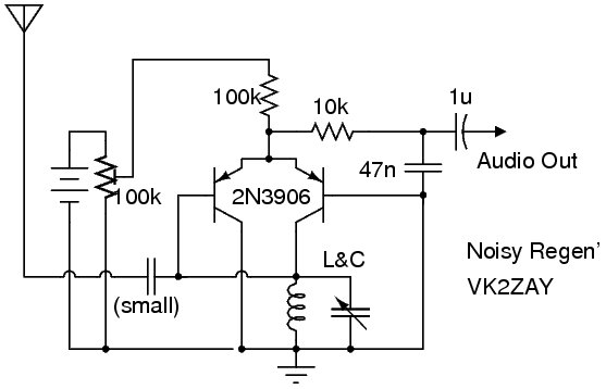
The following circuit illustrates a Noisy Regenerative Receiver Circuit Diagram. Features include a Noisy Regenerative Receiver Circuit, which simplifies the process of... The Noisy Regenerative Receiver Circuit is designed to amplify weak radio frequency signals while also incorporating a regenerative...
The circuit presented is an integrated circuit (IC) controlled emergency light. Its key features include automatic activation of the light during mains failure and a battery charger equipped with overcharge protection. In the absence of mains power, relay RL2...
A light dimmer circuit is utilized to adjust the brightness of a lamp to various levels. This dimmer circuit is designed specifically for incandescent lamps, and it is not suitable for use with fluorescent lamps. The light dimmer circuit typically...
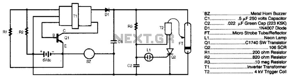
The burglar chaser is an effective accessory for any alarm system. It produces intense flashes of white light and generates a loud, irritating sound using a metal horn buzzer. Transformer T1 is connected to Q1, R1, and R2 to...
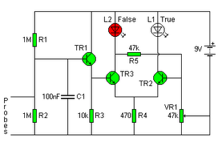
The following circuit illustrates a Lie Detector Circuit Diagram. Features include a capacitor that eliminates the 50Hz induced mains hum present in the circuit. The Lie Detector Circuit operates on the principle of measuring physiological responses, typically galvanic skin response...
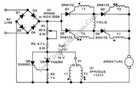
This is a motor controller circuit that controls the speed and direction of series-wound motors. This circuit employs silicon controlled rectifiers (SCR). The motor controller circuit is designed to manage both the speed and direction of series-wound motors, which are...