
ujt triggering circuit
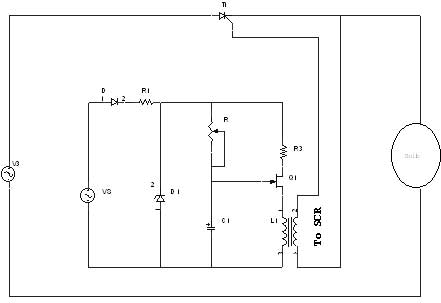
A unijunction transistor (UJT) operates primarily as a switching device and is widely used in pulse generation and timing applications. The unique structure of the UJT allows it to exhibit negative resistance characteristics, which are essential for its functionality in oscillator circuits. The emitter, being heavily doped, creates a significant potential barrier at the junction with the n-type material of the base.
In typical applications, the UJT is employed in relaxation oscillators where the charging and discharging of the capacitor through the resistor determines the frequency of the output pulse. The charging time is influenced by the value of the resistor (R) and the capacitance (C), while the discharging process occurs rapidly once the UJT is turned on.
The interbase resistance plays a crucial role in the operation of the UJT, as it affects the voltage levels at which the device switches states. The peak point voltage (V_P) is a critical parameter; it is the voltage at which the UJT transitions from its off state to its on state, allowing for the rapid discharge of the capacitor.
In a practical circuit, the UJT may be connected to additional components such as diodes or transistors to shape the output waveform or to enhance the triggering mechanism. The output pulse generated can be utilized to drive other circuits, providing a simple yet effective means of generating timed signals. The versatility of the UJT makes it an essential component in various electronic applications, including timing circuits, pulse generators, and even in some types of oscillators.A unijunction transistor (UJT) is an electronic semiconductor device that has only one junction. The UJT has three terminals: an emitter (E) and two bases (B1 and B2). The base is formed by lightly doped n-type bar of silicon. Two ohmic contacts B1 and B2 are attached at its ends. The emitter is of p-type and it is heavily doped. The resistance be tween B1 and B2, when the emitter is open-circuit is called interbase resistance. Initially the capacitor charges through R whose voltage is applied to the emitter of UJT. When the capacitor voltage reaches peak point voltage of UJT. the UJT will switch to on condition. Now the capacitor discharges through the output resistance. Thus the pulse is generated in the circuit. 🔗 External reference
Related Circuits
A real-time controller is a device designed to continuously manage household devices, both in real-time and according to a predetermined schedule. This article focuses on a series of real-time controllers utilizing the AT89C2051 microcontroller, which serves this purpose effectively....

Figure 1 illustrates an economical and straightforward Gate Alarm designed to operate using a small universal AC-DC power supply. IC1a functions as a fast oscillator, while IC1b serves as a slow oscillator. These two oscillators are integrated through IC1c...
The 555 timer is recognized as one of the most versatile and widely used integrated circuits globally. One of its potential applications is as a simple inverting Schmitt trigger. The 555 timer can be configured in various modes, including monostable,...
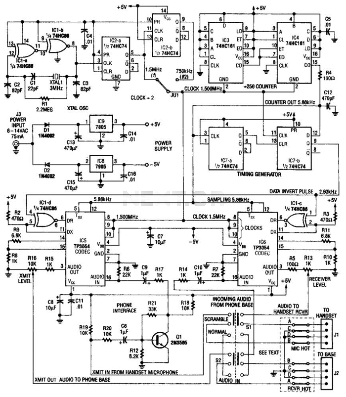
This circuit utilizes digital techniques to implement the frequency-inversion algorithm by digitizing the audio, inverting the sign of every alternate sample, and performing D/A conversion on the resulting data. The outcome is an inverted frequency spectrum. Additionally, the circuit...
The circuit described can connect two telephones in parallel and function as a two-line intercom. Typically, a single telephone is connected to a telephone line. When another telephone is needed at a distance, a parallel line is utilized for...
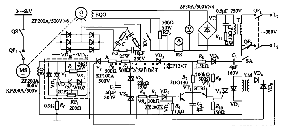
The circuit depicted in Figure 16-105 illustrates a synchronous motor. The components include BQ, which represents its field winding, and G, which denotes the AC excitation for the motor. The notation BQG indicates the field winding, with an empty...