
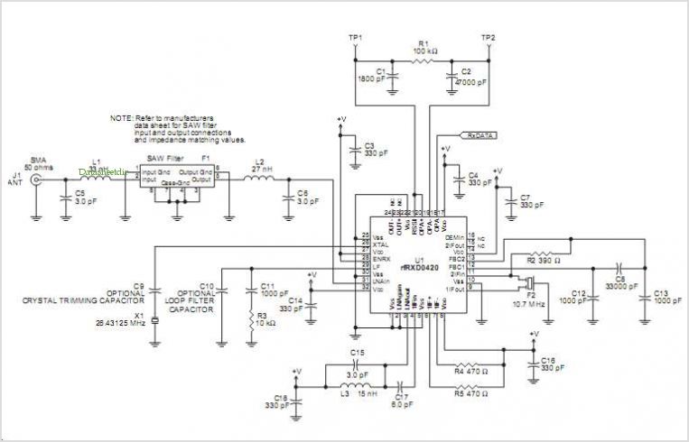
Rfrxd0420 Ask Receiver Reference Design
The RFRXD0420 and RFRXD0920 radio receivers are designed for efficient signal processing in short-range communication applications. These devices are particularly suited for scenarios where space and cost are critical factors. The compact design allows for easy integration into various systems, making them ideal for consumer electronics, remote control systems, and wireless sensor networks.
The operational frequency ranges of the RFRXD0420 and RFRXD0920 enable a variety of applications. The RFRXD0420's frequency range of 300 MHz to 450 MHz is commonly used for industrial and commercial applications, while the RFRXD0920's range of 800 MHz to 930 MHz is suitable for consumer electronics and amateur radio.
Both receivers support multiple modulation schemes, including ASK, FSK, and FM, providing flexibility for different communication protocols. This versatility allows designers to select the most appropriate modulation method based on the specific requirements of their application, such as data rate, power consumption, and range.
Integration with Microchip Technology Inc.'s rfPIC and rfHCS series of RF transmitters allows for seamless communication between transmitter and receiver, ensuring reliable data transmission. This compatibility streamlines the design process, as engineers can utilize existing modules without the need for extensive redesign.
In summary, the RFRXD0420 and RFRXD0920 are efficient, versatile, and cost-effective solutions for short-range radio communication, suitable for a wide range of applications in both consumer and industrial sectors.rfRXD0920 The RFRXD0420 RFRXD0920 are low cost, compact single frequency short-range Radio receivers requiring only a minimum number of external components for a complete receiver system. The RFRXD0420 covers the receive frequency range of 300 MHz to 450 MHz and the RFRXD0920 covers 800 MHz to 930 MHz.
The RFRXD0420 and RFRXD0920 share a common ar chitecture. They CAN be configured for Amplitude Shift Keying (ASK), Frequency Shift Keying (FSK), or FM modulation. The RFRXD0420 RFRXD0920 are compatible with rfPIC and rfHCS series of Rf Transmitters By Microchip Technology Inc.
🔗 External reference
Related Circuits
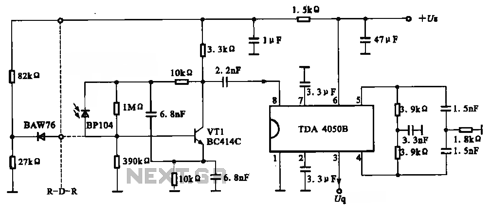
The circuit depicted is an infrared receiver circuit. It primarily consists of an infrared remote control signal switching circuit, designated as VRI, along with signal amplification, filtering, and rectifying integrated circuits, specifically the TDA4050B. The BP104 component serves as...
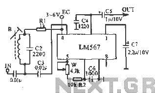
This figure illustrates the schematic of the LM567 SCA broadcast reception information machine. The LM567 serves as a narrow-band phase-locked loop designed primarily for SCA broadcast demodulation. The configuration includes a potentiometer (W) and capacitor (C6) that determine the...
The regenerative circuit is essentially an oscillator circuit equipped with gain control, enabling the user to fine-tune the feedback to a level just below oscillation or, frequently, just above the critical threshold to produce a small oscillation. Typically, a...
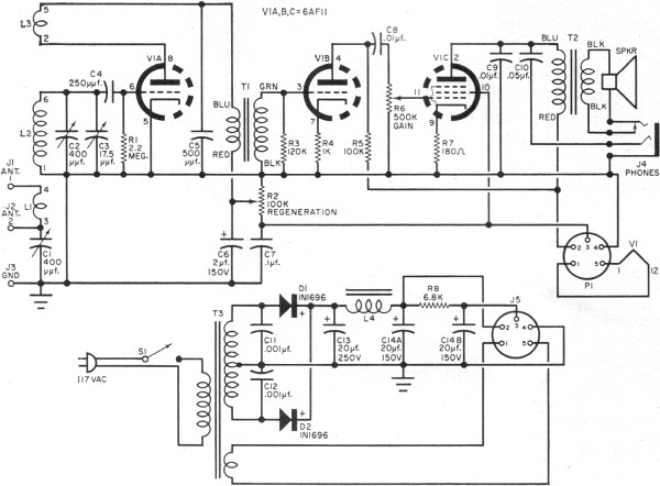
RF Cafe visitor David M. requested the scanning and posting of an article from the January 1963 edition of Popular Electronics, authored by Philip Hatfield from the Receiving Tube Department of General Electric. The article describes a straightforward design...
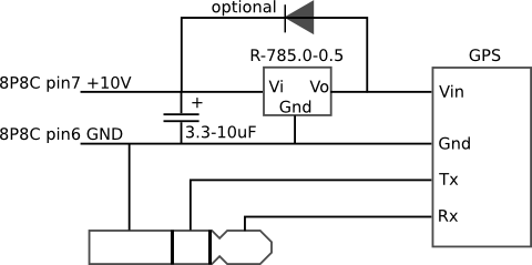
The mobile rig, a Kenwood TM-D710E, required a GPS receiver for APRS use. The GPS-710 was not readily available and was quite expensive, prompting the decision to build a custom solution. A Royaltek RGM-3600 GPS receiver was purchased on...
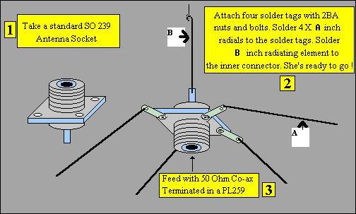
Two aluminum rods, each of length "L" in meters, are connected through an insulator as illustrated in the figure. A 75-ohm cable is fed from the center, similar to a conventional TV antenna. This configuration describes a basic antenna system...