
gps receiver for kenwood tm d710e
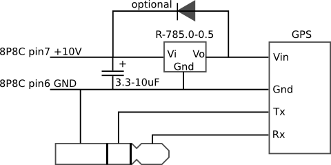
The circuit design incorporates several key components: the Royaltek RGM-3600 GPS module, a Recom R78 DC-DC converter, and an RJ45 Y adaptor. The GPS module communicates over RS-232, which is compatible with the Kenwood TM-D710E's display head. The Y adaptor allows for convenient access to the power and data connections. The DC-DC converter steps down the voltage from the +10V line to the required 5V for the GPS module, ensuring efficient operation. The addition of an input capacitor and blocking diode enhances the stability and protection of the circuit, preventing potential damage from voltage spikes or transients. The epoxy used to secure the components not only provides mechanical support but also serves as an insulating layer, reducing the risk of short circuits. The use of double-sided foam tape for securing components within the plastic enclosure provides flexibility and ease of assembly while maintaining a tidy appearance. The choice of cables and connectors ensures reliable data transmission from the GPS module to the display head, with the planned modifications for angled jacks improving the overall layout. The system's low power consumption allows for continuous operation without significant battery drain, making it an efficient solution for APRS applications.My mobile rig, a Kenwood TM-D710E, needed a GPS receiver for APRS use. The GPS-710 wasn`t readily available and, besides, is quite expensive. I therefore decided to build my own. I found a Royaltek RGM-3600 GPS receiver on eBay for less than £20. This is a very good SiRF III based receiver. The magnetic case made a nice fridge magnet as only the bare module was needed. Although the listing didn`t mention it, this turned out to be the RS-232 version of the module. If it had been the TTL version, I would have needed an additional MAX232 level converter. The module pinout is available here. Bob WB4APR (yes, that Bob) has very helpfully provided the pinout of the RJ45 (okay, 8P8C) connector on the TM-D710 display head. It shows that pin 6 is ground and pin 7 is +10V. This is a handy place to leech a few tens of milliwatts for the GPS receiver. I decided that the easiest way to get access to the +10V pin is by repurposing a RJ45 Y adaptor. Apparently these splitters are sometimes used in ISDN installations. I bought mine from Maplin for £5. 99. The male end of the adaptor isn`t ideal for soldering but a little bit of work with a craft knife exposes the contacts enough to solder wires into them.
Because the result is a bit fragile, I decided to cover the solder joints with epoxy. There are better adaptors that would be easier to tap into. The GPS requires a 5V power supply. I wanted to make sure the system draws as little power as possible, so I used a Recom R78 series switching DC-DC converter from Rapid. The R78 is a small self-contained device that`s pin compatible with the 78xx linear regulators so it`s trivially easy to use.
I decided to add an optional input capacitor and blocking diode for extra protection. The whole assembly was then secured onto the Y adaptor with epoxy to minimise mechanical stress. I happened to have a suitable plastic box for the parts. The rectangular cutout is made with a craft knife. All parts are installed in the box with double-sided foam tape. I made two short (~10cm) cables to connect the GPS to the display head, a 2. 5mm stereo and a RJ45. Both are wired straight through. I`m planning to replace the jack lead with one with 90 degrees angled jacks for neatness. The box is attached to the back of the display head with velcro. The fact that the receiver antenna sits vertically does not seem to matter. The +10V is supplied even when the radio is off. In the off state the rig seems to draw about 40 mA of current from the battery. Some of this is for the standby state of radio and some, probably most, is for the GPS. Overall that`s a negligible amount so I can just leave the GPS on all the time. This is good as the module seems to default to 19200 baud if left unpowered for a long time. The Kenwood only supports baud rates up to 9600, so I had to change the baud rate using the serial terminal on my computer and a suitable interface cable. 🔗 External reference
Related Circuits
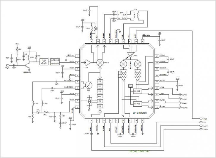
The PB1009K is a silicon monolithic integrated circuit (IC) designed for GPS receivers. This IC incorporates a complete voltage-controlled oscillator (VCO), a second intermediate frequency (IF) filter, a 4-bit analog-to-digital converter (ADC), and a digital control interface, all aimed...
The challenge in amplifying weak radio signals lies in the simultaneous amplification of noise. The quality of the received signal is influenced by the level of background noise, which may include man-made interference or static. In this design, the...
The new project utilizes old analog satellite receiver tuners that require modifications to disable the AFC and set the AGC to maximum gain. The output generated is a 480 MHz IF signal. The IF converter may consist of a...
The MAX2385 and MAX2386 LNA mixer integrated circuits (ICs) are designed for CDMA, cdma2000 1x, and GPS applications. These ICs are optimized for the Japanese frequency band of 832 MHz to 870 MHz and can also be configured for...
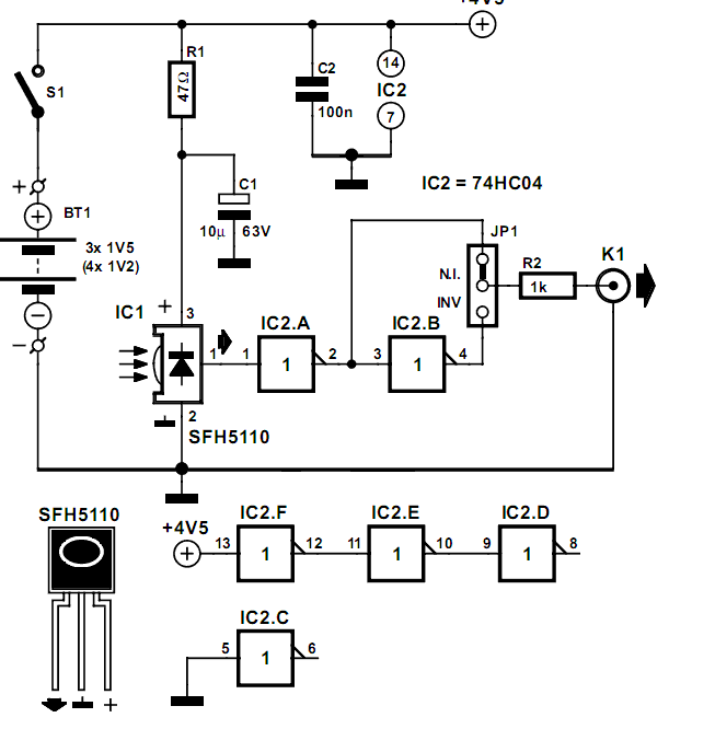
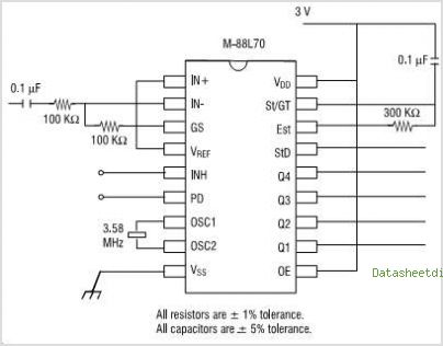
Many audio systems consist of separate units, and due to economic reasons, only the amplifier is equipped with a remote control receiver module. In audio system designs where components are split into separate units, it is common for only the...
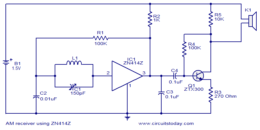
The circuit diagram of the single-chip AM radio is designed around the IC ZN414Z, which consists of ten transistors tuned for radio frequency reception. The single-chip AM radio circuit utilizing the ZN414Z integrated circuit (IC) is a compact and efficient...
Warning: include(partials/cookie-banner.php): Failed to open stream: Permission denied in /var/www/html/nextgr/view-circuit.php on line 713
Warning: include(): Failed opening 'partials/cookie-banner.php' for inclusion (include_path='.:/usr/share/php') in /var/www/html/nextgr/view-circuit.php on line 713