
Ring-Around LED Flasher

The ring-around LED flasher circuit is designed to create a visually appealing light effect by alternating the illumination of two pairs of LEDs. The circuit typically consists of a microcontroller or a timer IC that generates a control signal to manage the timing of the LEDs.
In a standard configuration, two LEDs are connected in series with current-limiting resistors to ensure that they operate within their specified voltage and current ratings. The microcontroller or timer IC is programmed to activate the first pair of LEDs while simultaneously deactivating the second pair. After a predetermined interval, the states of the LEDs are reversed, resulting in a continuous flashing effect.
The timing cycle can be adjusted by changing the values of the timing components, such as resistors and capacitors, associated with the timer IC or microcontroller. This allows customization of the speed at which the LEDs alternate, providing flexibility for different applications.
Power supply considerations must also be addressed, ensuring that the circuit operates within the voltage range suitable for the selected LEDs and control components. Additionally, the use of a breadboard or PCB can facilitate prototyping and assembly, allowing for easy modifications and testing of the circuit design.
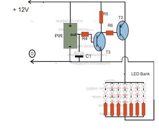
Overall, the ring-around LED flasher circuit is an effective way to create dynamic lighting displays, suitable for decorative purposes, signaling, or as part of larger electronic projects.This schematic diagram shows a ring-around LED flasher circuit. This circuit will turn off two LEDs and turn on the other two until the timing cycle reverses 🔗 External reference
Related Circuits

More: The input data contains a brief description with no additional context or information provided. In the realm of electronics, a circuit schematic typically serves as a visual representation of an electrical circuit. It illustrates the various components such...

This circuit offers a cost-effective alternative to the LM3915 series LED displays. It utilizes a square-wave oscillator constructed with two CMOS analog switches, which alternately select the right and left channels for monitoring and display. The chosen signal is...

Most PC enclosures provide only a single LED to indicate hard disk access, which is connected to the motherboard via a two-pin connector. However, this LED only functions with IDE drives, and if a SCSI disk controller is installed,...

The LED indicator in this project can be used for bike indicators or car direction indicators. A 555 timer and a BCD 7490 are utilized along with several resistors, exceeding 100 in total across various electronic projects. The circuit employs...

The flash rate is determined by CI and R4. The LEDs flash alternately. The circuit in question utilizes a timing mechanism where the flash rate of the LEDs is primarily governed by the capacitor CI and resistor R4. This configuration...
The circuit is an LED driver that responds to ambient light as well as the presence of an intruder, varying its illumination accordingly. Additionally, it includes an ambient light sensor to turn the LEDs on and off, and a...