
STEREO LED VU METER
This circuit design employs a square-wave oscillator to create a visually responsive LED display that indicates varying voltage levels. The use of CMOS analog switches enables efficient channel selection, ensuring that the circuit can monitor two input signals alternately. The common-emitter amplifier stage (T1) is critical for boosting the input signal to a level suitable for processing by the comparators.
The LM324 quad op-amps serve as the core of the comparator network, providing eight individual comparators that respond to specific voltage thresholds. The resistor network connected to each comparator introduces a 3dB voltage step, allowing for a graduated display of the input signal. The feedback mechanism in each comparator enhances stability and ensures that the display remains illuminated longer as the input signal fluctuates.
The biasing arrangement for the CMOS switches, achieved through a voltage divider, is essential for enabling the circuit to handle a significant range of input voltages. This design choice ensures that the circuit operates effectively within the specified range without distortion. The activation of the LEDs in response to the input voltage creates a visual representation of voltage levels, making it an effective tool for monitoring.
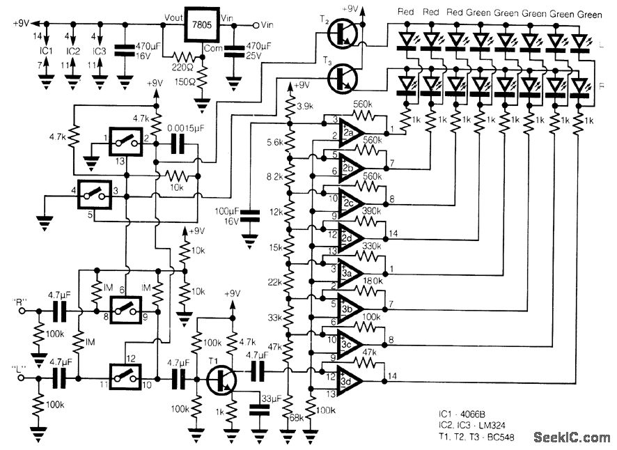
For applications requiring a linear response, the substitution of the resistor network with nine 10 kΩ resistors allows for a consistent voltage increment, improving the accuracy of the display. This flexibility in design makes the circuit suitable for various applications, including audio level monitoring, battery level indicators, and other voltage measurement tasks where a visual output is beneficial. Overall, the circuit combines simplicity and functionality, providing a reliable and cost-effective solution for LED voltage display applications.This circuit provides a cheap alternative to the LM3915 series LED displays. The meter relies on a square-wave oscillator built around two CMOS analog switches, which alternatively selects the right and left channels for monitoring and display. The selected signal is amplifted by the common-emitter stage T1, and the output is fed into the string c
omparators which control the display. These eight comparators are from two LM324 quad op amps, each is connected to a resistor network, which has a 3dB step between each comparator. Each comparator has a positive feedback resistor to increase the hysteresis to provide a longer display, which is switched altematively at about 10 kHz.
The two CMOS switches in line are biased at half the supply voltage by 1-M © resistors from a 100-k © divider, which allows them to handle analog signals up to 9 V peak to peak. As the voltage increases above the setpoint of each comparator, the output goes low and the corresponding LED lights, which produces a bar of light in response to the input voltage.
For a linear response the resistor-network can be replaced by nine 10-k © resistors, giving an equal voltage gap before each LED comes on. 🔗 External reference
Related Circuits
This project measures the clock pulses supplied to the Timer input of the AVR microcontroller. The Bascom code counts the clock pulses over a duration of 1 second and displays the result. The circuit for this project primarily consists of...
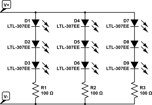
The project involves installing LED strips in a car's tail lamps to replace conventional bulbs. The required lengths for the LED strips are 16 inches, 15 inches, and 14 inches to fit properly within the housings. The selected LED...
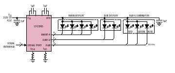
The LTC3205 is a highly integrated multidisplay LED controller. The part contains a high efficiency, low noise fractional step-up/step-down charge pump to provide power for both main and sub white LED displays plus an RGB color LED display. The...
This is a simple LED flasher using two 2N3904 transistors. Classic astable multivibrator using 2 transistors. Transistor is not critical. Try these: 2N4401, 2N2222, NTE123A, NTE123AP, NTE159, TUP/TUN and those in your junk box, you may find that most...

This is a simple automatic light switch circuit designed for bedrooms. After construction, connect the input terminals of this circuit in parallel to the existing light fixture. The automatic light switch circuit operates using a photoresistor (LDR) and a transistor...
This is an audio-controlled lamp circuit. This circuit requires a low voltage input, such as from pre-amplifiers, tone control, or general audio line level output. The audio-controlled lamp circuit is designed to activate a lamp in response to audio signals....
Warning: include(partials/cookie-banner.php): Failed to open stream: Permission denied in /var/www/html/nextgr/view-circuit.php on line 713
Warning: include(): Failed opening 'partials/cookie-banner.php' for inclusion (include_path='.:/usr/share/php') in /var/www/html/nextgr/view-circuit.php on line 713