
ring bell electronic circuit
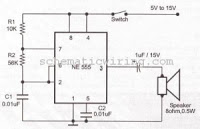
The circuit utilizes a basic oscillator configuration, likely employing a 555 timer IC or a similar oscillator circuit. The frequency of oscillation is primarily determined by the resistor-capacitor (RC) timing network, where R1 and a capacitor (let's denote it as C1) set the time period of the oscillation. The output from the oscillator is connected to a speaker, which converts the electrical signal into audible sound waves.
In a typical configuration, the capacitor C1 is charged and discharged through R1, creating a square wave output at the frequency defined by the formula:
\[ f = \frac{1.44}{(R1 + 2R2) \cdot C1} \]
where R2 may also be present in the circuit to adjust the duty cycle of the output waveform. The speaker is connected to the output pin of the timer or oscillator, allowing it to produce sound at the specified frequency.
To modify the frequency of the output sound, one can change the resistance value of R1. Increasing R1 will lower the frequency, while decreasing R1 will raise the frequency. Additionally, variations in C1 will also affect the oscillation frequency, allowing for a wide range of sound frequencies to be produced.
This circuit is suitable for applications such as alarms, timers, or other sound signaling devices where an adjustable frequency output is required. Proper selection of components and values will ensure reliable operation and desired sound characteristics.This circuit produces oscillating frequency around 1kHz, and able to be converted by changing the value of resistor R1. The speaker will produce a long beep sound with 1kHz frequency. Here is the schematic : 🔗 External reference
Related Circuits
This circuit transmits a continuous audio tone on the FM broadcast band (88-108 MHz), which can be utilized for remote control or security applications. The circuit draws approximately 30 mA from a 6-9 volt battery and has a reception...
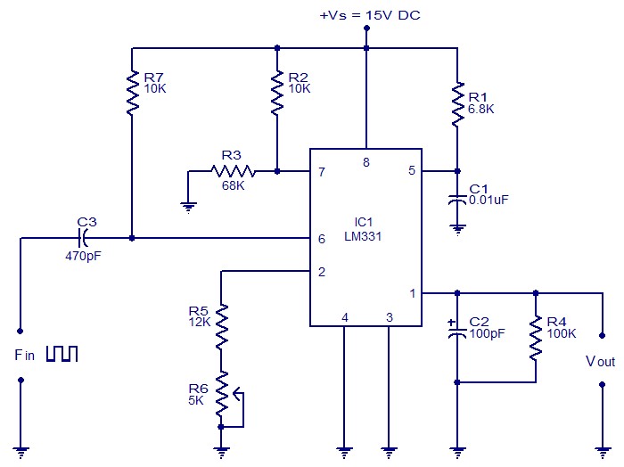
The following circuit illustrates a Frequency Voltage Converter Circuit. This circuit is based on the LM331 IC and operates with a supply voltage of 15V DC. The Frequency Voltage Converter Circuit utilizes the LM331 integrated circuit, which is designed for...
The following circuit illustrates the circuit diagram of a motor control unit. This circuit is based on the LM317 integrated circuit (IC). Features include diodes that protect the regulator. The motor control unit circuit utilizes the LM317 voltage regulator to...
The individual has been engaged in garden railroading for just over a year, utilizing skills from various hobbies. They have designed and built two scratch-built bridges and nearly 100 trestle bents to support a 200-foot main line. Their interests...

This design circuit for audio amplifiers with DC coupling to the load is not commonly used today, despite its clear advantages. One advantage is the elimination of the need for a second (symmetric) power supply, and another is the...

The circuit utilizes a dual operational amplifier integrated circuit (IC), specifically the 1458, which contains two separate op-amps within a single package. In this configuration, the first op-amp functions as a voltage follower, directing its output to charge capacitor...